8 Designing a Kick Drum
This chapter focuses on sound design for synthesizing a specific sound, a kick drum, as well as the problem solving that accompanies that process. The goal is to outline and emphasize the thinking process rather than presenting a recipe for a kick drum sound. By understanding the thinking process, you should be able to apply it to new sounds that you want to synthesize in the future.
Before proceeding, a quick disclaimer on the term "sound design" and the narrow usage of that term here. Sound design is a widely-used term that has deep roots in the film and theatre industries. It encompasses all aspects of creating sound, including performance and editing. Even in the music production industry, sound design includes editing, mixing, and processing recorded sound. Herein sound design refers to only the creation of sounds and effects using modular synthesis.
8.1 Problem solving for sound synthesis
Let's revisit and expand upon the problem solving approach introduced in Chapters 1 and 4. The general problem solving stages are:67
- Understand the problem
- Make a plan
- Implement the plan
- Evaluate the solution
The make/implement a plan stages of problem solving involves building a model by connecting modules together with patch cables, as we've covered in the last few chapters. While reasonable at first glance, the above problem solving approach is much more useful if it is expanded and elaborated in the context of sound design. Below is my interpretation of general problem solving68 and computational thinking principles69 70 as they fit into these stages.
8.1.1 Understand the problem
The problem is to create a specific sound. It may be a natural, physically produced sound, a sound of unknown origin from a recording, or a sound that exists only in your mind. The key questions are then:
- What is the sound? What are its defining characteristics? How does it differ from other sounds?
- How is the sound made in real life? Do you understand the principles and mechanism for how the sound is created? If it doesn't exist in real life, how could it be made if it did?
- Is all the information needed to make the sound available? If it is not available, how could you get the information you need?
8.1.2 Devise a plan
This stage is the most complex because you must think about your thinking71. It's best to try to stay flexible and evaluate multiple alternatives so you can pick the most promising one. This will prevent you from wasting effort on suboptimal strategies.
There are many ways to solve a problem, and often a combination of approaches is required. Approaches in the list below require different levels of information and expertise.
- Guess and check is the simplest strategy, but if the guesses are uninformed, it is the same as blind search. Given the number of ways modules can be combined, there are too many possibilities for a blind search to be efficient. However, informed guesses can be efficient, and thoughtful exploration can lead to brand new ideas.
- Looking at related problems is sometimes called reasoning by analogy. The idea is to find a known solution to a similar problem and then adapt the solution to the current problem. To do that, you need to identify what parts of the solution should carry over and what parts shouldn't (also known as abstraction and generalization).
- Decomposing the problem is a very powerful strategy that is easily combined with other strategies. The key idea is to divide a complex problem into smaller problems that are easier to solve. Because there's often more than one way to decompose a problem, it can help to think deeply about different decompositions. For example, related problems might suggest decompositions, and a particular decomposition might create smaller problems you already know how to solve.
- Using a model of how sound is made in real life can help identify modules that correspond to that model. It can also help with deciding how to decompose a problem and identifying related problems.
- Working backwards is a data-driven strategy that easily combines with other strategies. Instead of using your perception of the sound or preconceived notions about the sound, this strategy analyzes the properties of the sound itself to identify key features like frequency spectrum and dynamics.
8.1.3 Carry out the plan (and replanning)
This stage involves both model building and keeping track of what's working and what isn't. Model building has been well elaborated in the last few chapters, but it's worth reminding that sometimes the model idea is correct but parameters, i.e. knob positions, aren't quite right. Additionally, sometimes the module type may be correct, but the specific choice in module isn't quite right for the effect to be achieved. For example, in a previous patch we looked at a flanger module that has an internal LFO that can't be completely disabled, so if your patch idea required flanging without an LFO controlling the offset, this would be a suboptimal choice. So it's important as you carry out the plan that you consider how issues like these might trick you into thinking that your solution isn't good when it actually is but just needs a little tweaking.
Keeping track of what working and what isn't can get rather involved for any amount of extended problem solving. Here are some strategies to help with managing alternative solutions to a sound design problem.
- Having evaluation criteria is absolutely essential because otherwise, you won't know if you succeeded. You also won't be able to say whether one solution is better than another. The simplest criteria might be a single scale, e.g. 1-10, whereas better criteria can have scales for the defining characteristics of the sound.
- Keeping notes like a list can help keep track of what has been done and prevent repeating solutions. If each solution is documented with its evaluation, it makes it easier to identify common solution elements that seem to be beneficial or not.
- Eliminating possibilities can help you avoid unpromising directions. If every approach with a certain element hasn't worked well, then you might consider avoiding those elements in future attempts.
- Using symmetry can similarly help you understand what elements are exchangeable in a solution and might help generate new approaches. For example, you might have an approximate solution but realize that a module or two could be substituted with something that has a similar function for a better effect.
8.1.4 Evaluate the solution
Because this is a design problem, there's never a single absolute solution. It's best to consider solutions relative to each other in terms of evaluation criteria. Additionally, if resources are limited, it makes sense to consider solutions in terms of efficient use of resources, i.e. does one solution use fewer modules than another. Regardless of whether the solution is better than one you already generated, its worthwhile pausing to consider what you can learn from this example both in terms of the current problem as well as other potential problems.
It may be obvious that the stages of problem solving blend into each other and that the process of solving problems is iterative. Especially in design problems, there is never an absolute end to the process because there is never a single absolute solution. Thus the process iterates until you are either satisfied with your best solution or run out of time.
8.2 Reviewing previous kick drum patches
Let's review the kick drum patches from previous chapters to outline the thinking behind them and consider how they could be improved. The evaluation criteria for the kick drum sound is that it should be realistic and clean (not muffled). This review in some sense reflects the notes you might keep while carrying out your sound design plan.
8.2.1 Sine with envelope
The first patch was presented in Section 5.2.1, and it used a sine wave with an envelope to control its amplitude.
Understanding the problem. The only identifying characteristic considered was that kick is a low frequency sound. We know an idealized membrane (like a drum head) is inharmonic from Section 3.3 so it doesn't make sense to use a harmonically rich waveform.
Devising a plan. Looking at related problems of generating sound, we used the fundamental patch of an oscillator through an envelope to control its amplitude to create a single pitched note. Our model of the sound in real life considered the vibration of the drum after the head was hit by the mallet.
Carrying out the plan/Evaluating the solution
No particular care was given to these stages because the goal at the time was to demonstrate clocks as a sequencer. However, we can do this now by reviewing the patch itself and the associated sound, both of which are presented in Figure 8.1. The sound gets a 5 for realism but a 10 for cleanliness. Altogether this was a pretty naive attempt.
Figure 8.1: Kick made using a sine wave with an envelope to control its amplitude.
8.2.2 Sine with an envelope plus noise burst
The second patch was in Section 6.5, and it extended the first by mixing in red noise with an envelope to control its amplitude.
Understanding the problem. The new identifying characteristic was the sound of a mallet contact on the membrane in addition to the resonant sound of the drum. Intuitively, this would be a bunch of short lived frequencies, i.e. noise.
Devising a plan. This patched used decomposition by breaking down the kick sound into two components and using the existing patch as a solution for one of the components. Our model of the sound in real life added the sound when the head was hit by the mallet.
Carrying out the plan/Evaluating the solution
As before, no particular care was given to these stages because the goal then was to demonstrate different types of noise. Reviewing the patch itself and the associated sound presented in Figure 8.2, the realism in the sound has improved a bit (6) but also dropped in cleanliness (8). Of course it might be possible to improve on it by tweaking the noise envelope or the mix levels a bit more.
Figure 8.2: Kick made using a sine wave with an envelope to control its amplitude and mixed with red noise through an envelope to control amplitude.
8.3 Alternative approaches
We need strategies to develop alternative approaches if we're going to improve on these kick drum patches. The most relevant problem solving stages to consider are understanding the problem and devising a plan.
8.3.1 Improving our understanding of the problem
Let's return to the understanding the problem stage: can we come up with more defining characteristics of the sound or elaborate on how the sound is made in real life? Personally, I can't come up with anything beyond what's already been said. However, we can turn to the Internet to see what research has been done on the acoustics of kick drums for more ideas.
One acoustic study found that the frequency of the kick drum isn't constant as we assumed but rather changes very quickly from a higher pitch to a lower pitch (a drop of about 5 Hz)72. The presumed mechanism for this behavior is that the drum head's tension is very high just after it has been struck, and so it vibrates at a higher frequency until is resumes its initial position. We can operationalize this in modular using an envelope to control the pitch of the sine wave so that it goes high and then decays to the fundamental pitch. Similarly we can envelope the pitch of the noise. Since our noise module doesn't have frequency control, we can control the pitch of the noise using a filter on the noise module, and controlling the cutoff of the filter with an envelope. This raises another idea: we probably don't need low frequency noise below the fundamental, so let's use another filter, a high pass filter, to remove that noise to get a cleaner kick. Try patching these improvements into the last kick patch using the button in Figure 8.3.
Figure 8.3: Virtual modular for a kick drum using a sine mixed with noise where both have frequency controlled, either by envelopes or by filters.
A version of this patch with my specific settings is shown in Figure 8.4 along with a recording of the sound. It seems much improved compared to the last version in realism (8) and cleanliness (9).
Figure 8.4: Kick made using a sine wave with an envelope to control its amplitude and mixed with red noise through an envelope to control amplitude, with additional envelope control of initial frequency of the sine and band-pass filtering of the noise.
8.3.2 Devising new plans
What more can be done with this patch? The problem has been decomposed into generation of a fundamental and a noise burst, each with their own envelopes to control dynamics. If we consider related problems, we recently learned two ways of generating a fundamental that doesn't use a VCO. First, we can ping a resonant filter. We saw in Section 7.2.4 that pinging can give a somewhat natural plucky or percussive sound because the ping acts like a dampened oscillator. Second, we can use a waveguide as shown in Section 7.3. The waveguide also created a plucky sound, but that was much more string like. If we consider the symmetry between these two approaches and a VCO sine wave with an envelope, we realize that we can substitute these into our last patch to see if the sound is improved. Try patching a resonant filter in place of the VCO sine wave with an envelope using the button in Figure 8.5.
Figure 8.5: Virtual modular for a kick drum using a resonant filter mixed with noise where both have frequency controlled, either by envelopes or by filters.
A version of this patch with my specific settings is shown in Figure 8.6 along with a recording of the sound. It sounds much more realistic, perhaps because of the way the resonant filter handles the dampened oscillation (9) However it is also a bit muffled and loses out on cleanliness (6). One of the problems we seem to have with this approach is a lack of control of the frequency of the fundamental. The cutoff and resonance parameters affect both the initial transient as well as the body of the kick, whereas with a sine wave there was better separation in control of these two phases.
Figure 8.6: Kick made using a resonant filter mixed with red noise, with additional envelopes to control of initial frequency and resonance of the filter and band-pass filtering of the noise.
Let's see if the waveguide would be any better than the resonant filter, both in terms of sound and our ability to control the sound. Try patching a waveguide in place of the resonant filter using the button in Figure 8.7.
Figure 8.7: Virtual modular for a kick drum using a waveguide mixed with noise where the noise frequency is controlled by filters.
A version of this patch with my specific settings is shown in Figure 8.8 along with a recording of the sound. The sound seems worse and is more like a bass string pluck than a kick drum. So it sounds realistic but the wrong instrument (4), and the sound is a bit muffled too (6). As with the resonant filter, it seems the problem in making this patch work towards our goal is the difficulty in controlling specific aspects of the sound, since any one parameter changes seems to affect multiple aspects of the sound at once.
Figure 8.8: Kick made using a waveguide mixed with red noise, with additional envelopes to control of initial frequency and resonance of the filter and band-pass filtering of the noise.
Personally my favorite of these patches so far is the resonant filter for the overall realism and quality of sound, but I suspect that in some contexts it would muddy up a mix, i.e. it's not clean enough for some uses.
8.3.3 Working backwards
So far the approach has been to create "a" kick sound, one that scores highly on realism and cleanliness. But what if we wanted to synthesize a kick sound based on a recording of a real kick? We'd need more information to do this, specifically:
- A recording of the sound
- A diagram of the wave shape of that sound
- A diagram of how the frequency spectrum of the sound changes over time (a spectrogram)
- Diagrams of frequency spectrum at key time points in the sound
Unfortunately, the modules currently available in VCVRack/Cardinal are insufficient for most of the diagram needs. There are no modules that produce quality spectograms, and the tools for frequency spectra (like Sassy scope) are too coarse/noisy to give good information. We can use some additional software to help analyze the sound instead, and since this book is written using the R programming language, the analysis below uses that language. You could reasonably install R along with the libraries used below and run the commands yourself with your own sound files, or you may already have access to other software that would create spectrograms and frequency spectra, like Audacity73.
Figure 8.9: Kick recording used as the reference sound. Sound © Mattgirling/CC-BY-SA-3.0.
The real kick recording we'll use is presented in Figure 8.9. A spectrogram of this recording is presented in Figure 8.10. A spectrogram is merely the frequency spectrum of a sound over time. Because frequency spectra already have two dimensions and this adds a third dimension (time), the amplitude of each frequency is shown using color instead of an axis. The R code below loads the kick sound file and then creates a spectrogram with a maximum frequency of .7 kHz and uses 20 \(\mu Pa\) as 0 dB.
s <- tuneR::readWave("images/kick2.wav")
seewave::spectro(s,flim=c(0,.7),osc=T,dBref=2*10e-5,heights=c(1,1))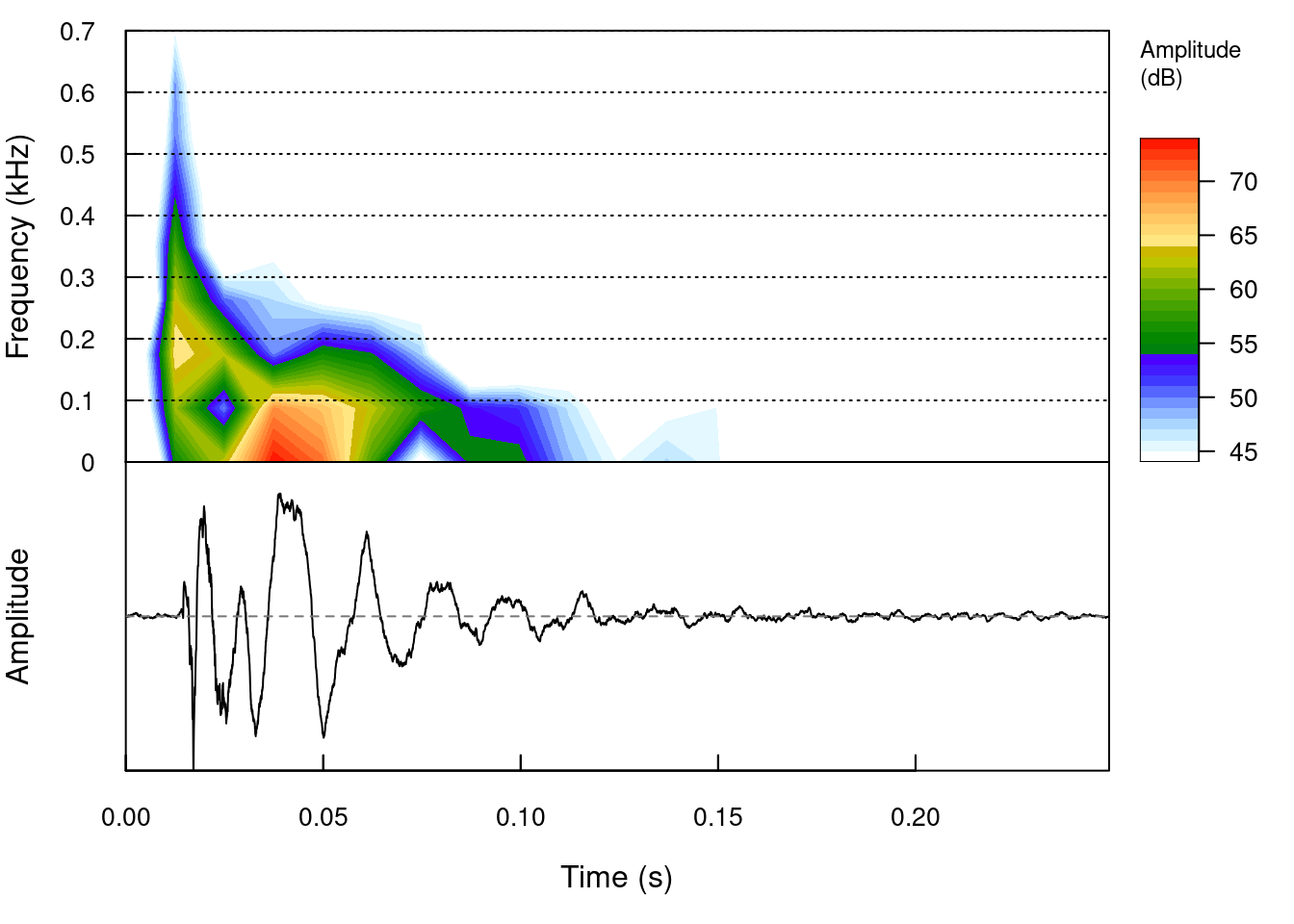
Figure 8.10: Spectrogram of the reference kick sound (upper) and corresponding wave (lower).
The spectrogram shows an initial burst of frequencies, with the most energy at about 200 Hz, followed by a lower range of frequencies with the most energy around 20-30 Hz. The corresponding diagram of the wave shape aligns with these regions and shows the initial burst has higher frequency until around 25 milliseconds, followed by a more regular decaying frequency. These two phases of the sound broadly align with our earlier patches, though our patches had both noise and fundamental beginning at the same time rather than as separate phases.
A closer examination of the frequency spectrum during the first phase shown in Figure 8.11 indicates a peak around 200 Hz but a fairly wide range of frequencies between 50 Hz and 350 Hz. The shape of the noise burst seems reasonably well aligned with the band pass filter used in the above patches, though some additional tuning of the shape of that filter may be needed to match this spectrum. The code below was used to generate the figure and look for frequency peaks.
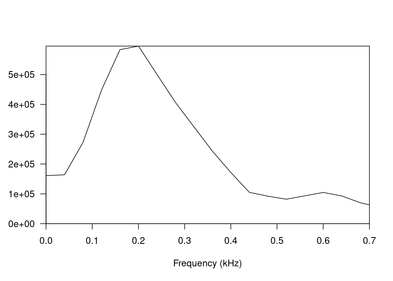
Figure 8.11: Frequency spectrum of the reference kick sound from 0 to 25 ms.
seewave::fpeaks(s.spec,f=44100,nmax=4,plot=F)| Frequency (Hz) | Amplitude (\(\mu Pa\)) | Harmonic ratio |
|---|---|---|
| 200 | 595,588.06 | 1.00 |
| 600 | 104,763.07 | 3.00 |
| 1201 | 78,152.55 | 6.00 |
| 1801 | 35,439.71 | 9.00 |
Table 8.1 reveals that the smoothed frequency spectrum in Figure 8.11 is hiding a number of frequency peaks, a few of which are harmonics of the fundamental 200 Hz. This suggests that while there is an initial noise burst, presumably from the mallet hitting the drum head, there is additionally an early harmonic resonant sound happening at the same time. Presumably this is the frequency-shifted sound discussed earlier, caused by the increased tension on the drum head shortly after impact, but a much higher frequency shift than previously patched.
A similar examination of the frequency spectrum during the second phase of the kick sound is shown in Figure 8.12. Unlike the first phase, there are multiple clear peaks in the frequency spectrum, with an apparent fundamental around 50 Hz. The code below was used to generate the figure and look for frequency peaks.
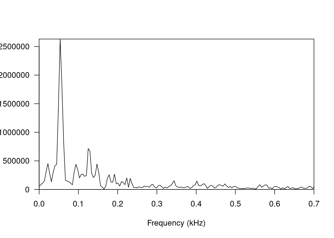
Figure 8.12: (ref:kick-spectrum-late)
seewave::fpeaks(s.spec,f=44100,nmax=4,plot=F)| Frequency (Hz) | Amplitude (\(\mu Pa\)) | Harmonic ratio |
|---|---|---|
| 22 | 452,508.80 | 1.00 |
| 54 | 2,630,931.40 | 2.40 |
| 94 | 438,928.40 | 4.20 |
| 125 | 715,718.10 | 5.60 |
Table 8.2 shows the frequency peaks in Figure 8.12. There are no harmonics of the lowest frequency, and interestingly the loudest frequency, 54 Hz, is not the lowest This aligns with our general assumptions about percussion being largely inharmonic.
Let's summarize the findings. The spectrogram reveals two distinct phases of the sound. The first phase, up to 25 ms, blends noise (mostly 0 to 400 Hz) with harmonics. The second phase, from 25 ms on, is inharmonic but with clear peaks.
There are many ways to model the above findings in modular, and we can get as complex as we want. However, to keep things simple, let's stay relatively close to previous patches and techniques that have already been introduced. Let's use three envelopes for three different sound sources: a band-passed noise source, an early harmonic sound, and a late inharmonic sound. For the non-noise sources, we can use separate oscillators for the partials (additive synthesis). All partials for a source will run through a mixer to produce the composite sound for that source, then all sources will run through a final stage mixer. Because there's clearly some room sound in the recording, run the final mixer output through a reverb to create a sense of space. Try patching this drum kick using the button in Figure 8.13.
Figure 8.13: Virtual modular for a kick drum using two oscillator banks mixed with noise where the noise frequency is controlled by filters.
A version of this patch with my specific settings is shown in Figure 8.14 along with a recording of the sound. It's not as close to the reference sound as I would have hoped, as it both sounds pitched higher in that initial harmonic sound and thinner in terms of noise frequencies. I suspect that there are extensive inharmonic partials that are characterizing the body of the sound. Nevertheless, the sound is quite realistic (10) and quite clean (8) especially since the reverb can be controlled independently. It's perhaps not fair to compare this sound to the previous kick sounds because it is so different and would likely be used in different contexts. Matching it to the previous kick sounds (rather than the reference recording) would likely involve a tighter decay on the harmonic sound and a drop in frequencies across the sine banks, which are currently pegged around 55 Hz vs. the 40 Hz of the previous kicks.
Figure 8.14: Kick made using two sine oscillator banks mixed with white noise with additional envelopes to control the decay of the sine banks and frequency of the band-pass filtering of the noise.