10 Modulating Controllers
This chapter extends Chapter 5 by introducing more advanced approaches to sequencing. Sequencing can be considered a kind of memory for musical events where the events can be stored and played back later. Obviously there are gaps between events because not all notes (or beats) play at once. This leads to the idea that sequencing involves both positive space and negative space: positive space where musical events occur and negative space elsewhere.
This idea of positive and negative space can be seen clearly in step based sequencers that allow steps without events, such as the trigger sequencers discussed in Chapter 5. However, a step-based conceptualization of sequencing leads to the limitation that a step should represent the smallest duration event, and such fine granularity naturally leads to more steps being empty. An event-based conceptualization that flexibly represents the start and end of each event, in contrast, has less need to explicitly define negative space. For example, consider a sequence with two notes, the first lasting 2 units, followed by 4 units of silence, followed by the second note lasting 1 unit. A step-based representation would use 7 steps and four of them would be empty. An event-based representation would use two events, one starting at time 1 and lasting 2 units and one starting at time 6 and lasting 1 unit.
In practice, modular sequencing often combines both step-based and event-based elements. The reason for combining both is that each has different strengths. To better appreciate these strengths, let's define three ideal properties of a sequencing approach and use it to evaluate alternatives. An ideal sequencing approach should allow:
- Compact representation of variations, i.e. in a minimal amount of space
- Ease of changes between variations
- Precise control of variations
It turns out that sometimes these properties are at odds with each other, such that different combinations of modules can outperform on some and underperform on others. As we examine different options in this chapter, we'll keep this properties in mind.
10.1 Modifying gates
One of the limitations of pure clock-based sequencing is that every gate starts on the beat. Unfortunately, syncopation, which emphasizes off beats, is widespread in modern music. The on-beat property of clock divisions is illustrated in Figure 10.1. If we consider the clock to represent quarter notes, then the gaps between clock gates are eighth note off beats, i.e. if we count 1-and 2-and 3-and 4-and, the off beats are 'and'.
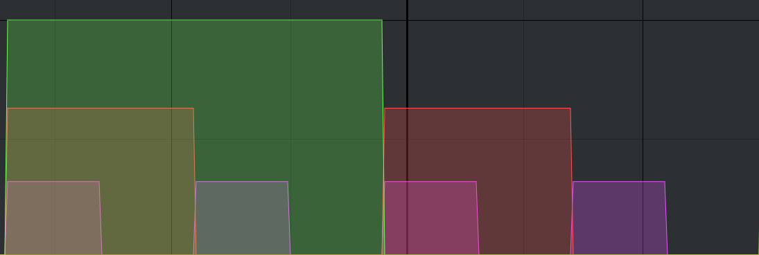
Figure 10.1: Four gates from a clock (small) overlaid with two gates from a /2 clock division (medium) and further overlaid by one gate from a /4 clock division (large). If we consider each clock gate as defining a quarter note, then all three gates occur on the first quarter note and the first two occur on the third quarter note, so the three gates are aligning only on beats.
Let's build a basic patch with clock divisions that illustrates this on beat property both in sound and visually on the scope. To keep things simple throughout this chapter, we will modify this percussion-oriented patch and note differences with sequencing pitches. All the modules and concepts in this patch were introduced in previous chapters, except for a new three-voice percussion module that can produce various sounds. Try patching up this basic percussion patch with clock divisions using the button in Figure 10.2.
Figure 10.2: Virtual modular for a basic percussion patch using clock divisions.
In light of the ideal properties for sequencing, the basic clock division approach allows both compact representation in terms of divisions and ease of changing between variations by changing divisions. However it lacks precise control because off beats are inaccessible. Other related complications include increasing the number of hits on a particular beat, sometimes called a roll and skipping a beat. All three of these variations can be approached by modifying existing gates, a concept that was first introduced in Section 5.2.3.2 for sequencing note duration. Since sequencing note duration is identical to sequencing gate duration, we'll look at only the other two techniques here.
Hitting an off beat can be accomplished using a gate delay module. A gate delay module receives an incoming gate (sometimes a trigger) and then create another gate at some time delay. If the time delay corresponds to the length of a beat, then the delayed gate will appear on the off beat. Try extending the last patch with a gate delay to move the open hat to the off beat using the button in Figure 10.3.
Figure 10.3: Virtual modular for a percussion patch using clock divisions and a gate delay to hit an off beat.
With respect to the three ideal properties, the delayed gate approach (combined with clock divisions) is still compact, a bit less easy (because setting the delay is a bit fiddly), and more flexible, though the offset is the same for each clock or clock division. Thus if we want variations of off beat or rolls, we need additional tools.
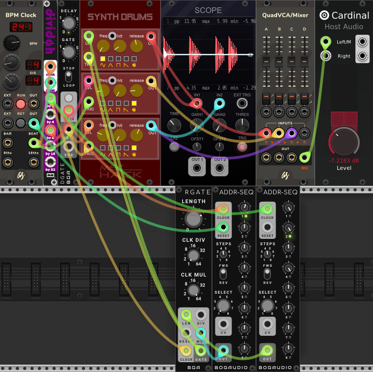
Drum rolls can be accomplished using a gate multiplier. Gate multipliers will generally need a control voltage telling them how many gates to make, which correspond to the number of hits in the roll. Thus an additional sequencer is needed to supply this control voltage. Try extending the last patch with a gate multiplier and associate sequencer to give the kick a double hit on the first beat using the button in Figure 10.4. Because the kick time is 4:4, the sequencer only needs four steps.
Figure 10.4: Virtual modular for a percussion patch using clock divisions, a delayed gate for an off beat hit, and a sequenced gate multiplier for multiple hits on the beat.
Returning to the three ideal properties, the gate multiplier approach (again combined with clock divisions) is a bit compact because it relies on another sequencer, a bit less easy (because setting the multiplier voltage is a bit fiddly), and more flexible because it allows different drum rolls on each step. Just as a sequencer was used to control the gate multiplier, a sequencer could be used to control the gate delay offset of the previous patch or drop a step by controlling the length parameter, as shown here.
It's clear that adding more sequencers to control these parameters increases flexibility but also makes the overall control less compact and changing between variations less easy. For example, if one wanted to replace a skipped step with a triple beat, one would have to adjust the length sequencer for a non-zero gate length, then adjust the multiplier sequencer to create multiple hits on that step, i.e. one would have to adjust multiple parameters for that step, and these parameters are spread across different sequencers. Is this suboptimal? Let's compare against other solutions before making judgment. One obvious alternative is to create the same pattern using standard step sequencers without any clock divisions. Try updating the last patch with a step sequencer for the off beat hat and the double beat kick using the button in Figure 10.5. Because the kick time is 4:4, the sequencer only needs four steps.
Figure 10.5: Virtual modular for a percussion patch using step sequencers for an off beat hit and multiple hits on the beat.
Contrast this approach with what we've done so far. The step sequencers are somewhat compact if the pattern can be decomposed into the smallest repeating loops, though not as compact as a clock divider. They are easy to change in some ways but not others. For example, if we decide we want a triple hit on a beat rather than a double, we need to increase the step resolution from two steps per quarter note to three steps per quarter note, which requires changing the entire kick pattern. Conversely, step sequencers have a high level of precision if one accepts increasing the number of steps arbitrarily to account for off beats, swing, or dilla, but this then sacrifices compactness. Note that the previous approaches with gate delays and multiplications achieved these results to an arbitrary degree without additional loss of compactness, i.e. we could have a 10 hits instead of 2 with the same gate multiplier patch.
10.2 Making gates with logic
Suppose we wanted to select the offbeats in our current pattern. Looking at Figure 10.1, the offbeats are simply where the the beats are not. So if we had a way of specifying "not beat," then we'd be able make a gate for the off beats. Boolean logic provides a way of specifying "not beat" and can further be used for more complex beat specifications.
Although it may seem intimidating at first, Boolean logic has just three basic operators, AND, OR, and NOT. AND means two things happen together, OR means at least one thing happens, and NOT means something didn't happen. If we represent something happening (like a gate) as 1 and not happening as 0, then these basic operators are summarized in Table 10.1.
| S1 | S2 | AND(S1,S2) | OR(S1,S2) | NOT(S1) | NOT(S2) |
|---|---|---|---|---|---|
| 1 | 1 | 1 | 1 | 0 | 0 |
| 1 | 0 | 0 | 1 | 0 | 1 |
| 0 | 1 | 0 | 1 | 1 | 0 |
| 0 | 0 | 0 | 0 | 1 | 1 |
Try updating the basic percussion patch with a NOT module to put the open hat on every off beat using the button in Figure 10.5. We'll build on this logic in the following patches.
Figure 10.6: Virtual modular for a percussion patch using clock divisions and the NOT operator to create gates for all off beat hits.
We can use logic to create other gates using combinations of the basic operators. For example, consider every other offbeat in Figure 10.1. These offbeats occur when the clock is not present and the /2 division is present. Try updating the last patch with an AND module to implement this logic using the button in Figure 10.7.
Figure 10.7: Virtual modular for a percussion patch using clock divisions and combining the NOT and AND operators to create gates for every other off beat hits.
Let's get even more specific with logic to match what we did previously with the gate delay, which was a single off beat. Since the last patch used every other off beat, we can use an additional operator to select just one of those beats. Again looking at Figure 10.1, we see that we can achieve this by using AND with our existing logic and next larger clock division. Try updating the last patch to implement this logic using the button in Figure 10.8.
Figure 10.8: Virtual modular for a percussion patch using clock divisions and combining the NOT and AND operators to create a single gate per bar, matching the previous delayed gate behavior.
Let's consider the three ideal sequencer properties, in terms of logic. The first application of NOT was quite compact, ease to change, and precise. However, as the logic became more complex, the sequencing became less easy. Contrast the last logic patch that needed three or four logical operators to what was previously accomplished by using a single gate delay. It appears that clock divisions with logic are most suited to regular repeating patterns, and that when patterns become less regular, other options may be easier.
10.3 Adding/removing gates with probability
Generally speaking, the more complex sequencing we want (i.e. irreducible to a simple pattern), the less compact our control will be. We can get around this limitation if we give up precise control of the sequencing by turning to probability. A probability specifies of the likelihood of an event, like a gate. In our current approaches, a gate either happens or it doesn't. However, if we assign some probability to a gate happening, more complex patterns emerge because sometimes the gate will happen and sometimes it won't.
Perhaps the easiest way to think about probabilistic gates is to think of them like coin flips. If we flip a coin and get a head, then the gate will be produced, otherwise no gate will be produced. How can we simulate a coin flip in modular? One way is to generate a random voltage and then compare it to a reference value. If the voltage is above the reference value, we count it as a head and produce a gate. We've already seen how to create random voltages with noise generators. The new idea here is a comparator, which is a module that accepts an incoming voltage \(V\), compares it to a reference voltage \(R\), and produces a high signal if \(V > R\).78 Because different noise spectra have different distributions of frequencies (and thus voltages), different noise spectra will give us different probabilities for the same reference voltage.
We can use the probabilistic gate idea to sequence all the percussion voices in our ongoing example. Since probabilistic gates would be completely random by definition, we'll structure them a bit using logic: a NOT to make two different voices alternate and an AND to combine two different noise signals for a lower probability. Try updating the last patch to drive all gates with probability and logic using the button in Figure 10.9.
Figure 10.9: Virtual modular for a percussion patch using probabilistic gates slightly structured with NOT and AND operators.
The output of this patch is much more complex than we could reasonably achieve using other sequencing methods, but it is also uncontrolled and not very musical, even when shaped a bit by logic. An alternative to randomly creating gates is to take an existing pattern but randomly drop gates. This can be implemented as simply as using noise source, a comparator, and an AND module that receives the output as well as the output for the normal gate. However, to get the random gates to align with the standard clock, we'll use a new module, a sample and hold module. A sample and hold module, when triggered, stores whatever voltage is present at its input and outputs that voltage until a new trigger is received, ignoring whatever input voltages occur in the meantime. By connecting a random gate to a sample and hold and triggering it with a clock, we can synchronize the random gate with our clock and have a clean signal for deciding to drop a gate or not. Note that if we wanted to produce V/Oct control voltage for random notes, we could similarly use sample and hold module directly connected to our random source, i.e. without a comparator. Try updating the previous logic patch that selected every other off beat to further consider a random gate using the button in Figure 10.10.
Figure 10.10: Virtual modular for a percussion patch using a probabilistic gate and logic to decide when to drop a gate from an otherwise non-probabilistic sequence.
As shown by these patches, probability can be used to create interesting variations in several ways. These methods are fairly compact and can switch between variations easily, however, there is a loss of control. Modules specifically designed for randomness typically have additional parameters that allow the user to define how random events should be, which can help mitigate this loss of control.
10.4 Speed variable clocks using LFOs
Recall one of the earlier challenges raised was to increasing the number of hits on a particular beat, skipping a beat, and accessing all possible beats (including off beats). We've tried to solve this problem using gate delays, logic, or an increased step resolution to access off beats and gate multipliers and increased step resolution to increase the number of hits on a particular beat. In each case, one technique would solve some problems but not others, with the exception of step resolution which has the problems previously discussed.
It turns out that we can achieve all three of these goals by running speed variable clocks, one for each percussion voice where we want to have multiple beats, skipping, or offbeats at different times. The idea is that when we want multiple beats, we speed the clock up; when we want to skip a beat, we slow the clock down almost zero, and that when we want to access an offbeat, we use the same sequencer we're using the speed up and slow down the clock. Because a clock is just unipolar rectangular waves, an LFO can be used as a speed variable clock. One of the additional benefits of this approach is that skipping a beat and doubling a beat are controlled by the same parameter, frequency. Contrast this with the previous approach using gate multiplication, where skipping a beat required an additional sequencer. We still need a master clock however to keep the LFOs in sync, which can be done by sending clock to their reset inputs, which resets them to the beginning of their waveforms.
Let's recreate the off beat open hat with a double kick on the first beat that we've used as a running example. Both of these voices will require their own LFO to serve as a clock, where each LFO has its frequency controlled by a sequencer. Try updating the previous patch with gate delay and gate multiplier to use sequenced LFOs instead using the button in Figure 10.11.
Figure 10.11: Virtual modular for a percussion patch using LFOs as speed variable clocks to achieve gate delays, skipped steps, and off beats using a single parameter.
As you can see, this approach is fairly compact but not as compact as using a gate delay and gate multiplier because we've explicitly represented a number of skipped steps. However it is now easier to change between variations, e.g. adding rolls on different beats or skipping different beats would not require changing the patch, and these can be controlled by a single parameter.
A variation of this approach, though perhaps a somewhat distant one, can be used to generate gate patterns without a clock. Simply mix LFOs at different frequencies to produce an irregular interference pattern that can then be run through a comparator to generate gates. If these need to be synced to a clock for uniform gate lengths, then the sample and hold method discussed in the previous section can be used. A clock can also be used to periodically trigger the reset of the LFOs, forcing the pattern to repeat.
10.5 Euclidean rhythms
We've mostly discussed sequencing where the patterns have been designed by hand, with the exception of probabilistic gate sequences and the recently mentioned sequenced generated by frequency-mismatched LFOs. What if there was a more predictable, more rule-like way of generating patterns? Euclidean rhythm is a recently discovered method that generates patterns in a rule-like way.79 This approach gets its name from the Euclidean algorithm for finding the greatest common divisor, which is the largest natural number that divides two numbers, \(a\) and \(b\) without a remainder. Here's how it works. Suppose \(a > b\). Then the algorithm divides \(a\) by \(b\) to get a remainder \(c\), e.g. \(8/5\) has remainder 3. If \(c=0\), then \(b\) is the greatest common divisor. Otherwise repeat by substituting b and c for a and b, e.g. 5/3 has remainder 2.80
To map the Euclidean algorithm to beats, suppose that we want to evenly distribute \(b\) beats over \(p\) positions, which we will call \(E( b, p )\). Positions with no beat are silent (\(s\)). Then we parallel the structure of the Euclidean algorithm and define division as pairing up the \(b\) and \(s\), with the unpaired \(s\) forming the remainder. The pairs substitute for \(b\), the remainder substitutes for \(s\), and the process repeats until the remainder is a single element or there are no \(s\). An example of this process is shown in Table 10.2 for \(E(5,13)\).
| a | b | c | Pattern | |
|---|---|---|---|---|
| 8 | 5 | 3 | |x|x|x|x|x|.|.|.|.|.|.|.|.| | |
| 5 | 3 | 2 | |x.|x.|x.|x.|x.|.|.|.| | |
| 3 | 2 | 1 | |x..|x..|x..|x.|x.| | |
| 2 | 1 | 0 | |x..x.|x..x.|x..| |
As shown in Table 10.2, Euclidean rhythms divide the number of beats across positions as evenly as possible. If \(b\) divides \(p\) without remainder, then there will be an equal number of silences between beats. It turns out that there is an even easier way to calculate Euclidean rhythms by using Bresenham's line algorithm: using the equation for a line, at each natural number \(x\), take the floor81 of \(y\). In this approach, \(x\) is equivalent to \(p\), each increase in \(y\) is equivalent to \(b\), and each lack of increase in \(y\) is equivalent to \(s\). The result of the algorithm is shown in shown in Figure 10.12. Note that the colored regions mark the closest fitting line with slope \(5/13\) where the line is constrained to move in square units - this is equivalent to distributing beats as evenly as possible across positions.
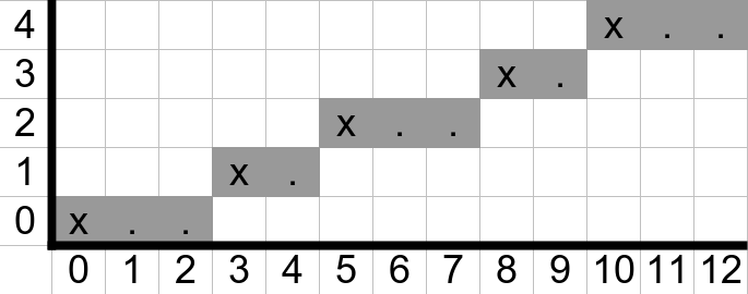
Figure 10.12: Example of Bresenham's line algorithm for the example \(E(5,13)\).
Euclidean rhythms can start at an offset into the sequence such that the skipped early portion is then added to the end. This is sometimes called a rotation, and different rotations are sometimes described as belonging to the same necklace. Let's apply Euclidean rhythms to the basic percussion patch from the beginning of the chapter. We'll use a special model that generates a Euclidean rhythm for each percussion voice, along with a trigger to gate module. Try updating that patch using the button in Figure 10.13.
Figure 10.13: Virtual modular for a percussion patch using Euclidean rhythms for each voice.
As you can see from the patch, Euclidean rhythms is very compact and flexible, since we can easily change the length of patterns without affecting the proportion of hits and vice versa, just by turning a knob. However, we also lose some precision. For example, it isn't possible to make a double hit on the first beat because Euclidean rhythms by definition evenly distribute beats. So again, we trade precision for compactness and flexibility. It's worth noting that Euclidean rhythms can also define scales. For example, \(E(5,12)\) selects notes in the major pentatonic scale, and \(E(7,12)\) selects notes in the diatonic scale C major.
10.6 Sequential switches
The focus up to this point has been on creating patterns, but music typically involves chains of patterns. While it would be possible to have repetitions of a pattern in a sequencer, this is less compact because any change to a step in the pattern would require changing that step everywhere the pattern was repeated. Instead it makes sense to consider each pattern as a chunk sequence these chunks. Sequential switches are type of module that makes it easy to switch between different patterns in a sequence.
Sequential switches are also known as multiplexers and demultiplexers. A multiplexer is used to send \(N\) different signals to 1 place (N:1), and a demultiplexer is used to send 1 thing to \(N\) different places (1:N). The signal can be anything, including audio, and the destination is selected either by a clock or control voltage. When the selection is done by clock, each clock advances the switch just like a clock advances a sequencer. When the selection is done by control voltage, different voltage ranges select different destinations so that the selection can go out of order.
As a concrete example, supposed you have a kick drum and you want to send it a pattern, and when that pattern finishes, send it another pattern. That is multiplexing because you have \(N\) patterns you are sending to 1 place, the kick drum. On the other hand, suppose you have a pattern that you'd first like to send to flute voice, and when that pattern finishes, send the same pattern to a violin voice, and so on. That is demultiplexing because you have 1 pattern that you are sending \(N\) different places. If this is confusing, it's best to assume multiplexing (N:1) as this seems to be the more common operation.
Let's look at a simple example of using a sequential switch. In the previous patch with a gate delay and gate multiplier, the kick had a double hit on the first beat, and this was repeated every four beats. Suppose we wanted to repeat every eight beats instead. One option is to fill up the sequencer with empty steps, but another option is to divide the eight steps into two sequences of four steps each. The first four step sequence is our original sequence, and the second four step sequence is just the kick clock division. A clock division matching the length of the patterns is sent to the switch to advance to the next pattern. Try implementing this patch using the button in Figure 10.14.
Figure 10.14: Virtual modular for a percussion patch using a sequential switch to alternate between patterns.
Using a switch in this way suggests a general strategy for sequencing. Since each of the techniques discussed in this chapter has its strengths and weaknesses with respect to compactness, flexibility, and precision, it makes sense to alternate between them depending on the needs of the sequencing problem at hand and use sequential switches to combine them into larger patterns.
10.7 Check your understanding
Which of the following is suitable for combining sequences into larger patterns?
Which of the following is not a problem for sequencing using clock divisions alone?
How many Boolean logic operators are there?
Which of the following is not a parameter of Euclidean rhythms?