

DISTRIBUTION STATEMENT A: Approved for public release; distribution is unlimited.
NONRESIDENT TRAINING COURSE
SEPTEMBER 1998
Navy Electricity and Electronics Training Series
Module 2—Introduction to Alternating Current and Transformers NAVEDTRA 14174
DISTRIBUTION STATEMENT A: Approved for public release; distribution is unlimited.
Although the words “he,” “him,” and “his” are used sparingly in this course to enhance communication, they are not intended to be gender driven or to affront or discriminate against anyone.
i
PREFACE By enrolling in this self-study course, you have demonstrated a desire to improve yourself and the Navy. Remember, however, this self-study course is only one part of the total Navy training program. Practical experience, schools, selected reading, and your desire to succeed are also necessary to successfully round out a fully meaningful training program.
COURSE OVERVIEW: To introduce the student to the subject of Alternating Current and Transformers who needs such a background in accomplishing daily work and/or in preparing for further study.
THE COURSE: This self-study course is organized into subject matter areas, each containing learning objectives to help you determine what you should learn along with text and illustrations to help you understand the information. The subject matter reflects day-to-day requirements and experiences of personnel in the rating or skill area. It also reflects guidance provided by Enlisted Community Managers (ECMs) and other senior personnel, technical references, instructions, etc., and either the occupational or naval standards, which are listed in the Manual of Navy Enlisted Manpower Personnel Classifications and Occupational Standards, NAVPERS 18068.
THE QUESTIONS: The questions that appear in this course are designed to help you understand the material in the text.
VALUE: In completing this course, you will improve your military and professional knowledge. Importantly, it can also help you study for the Navy-wide advancement in rate examination. If you are studying and discover a reference in the text to another publication for further information, look it up.
1998 Edition Prepared by DSC Ray A. Jackson
Published by NAVAL EDUCATION AND TRAINING
PROFESSIONAL DEVELOPMENT AND TECHNOLOGY CENTER
NAVSUP Logistics Tracking Number 0504-LP-026-8270
ii
Sailor’s Creed
“I am a United States Sailor.
I will support and defend the Constitution of the United States of America and I will obey the orders of those appointed over me.
I represent the fighting spirit of the Navy and those who have gone before me to defend freedom and democracy around the world.
I proudly serve my country’s Navy combat team with honor, courage and commitment.
I am committed to excellence and the fair treatment of all.”
iii
TABLE OF CONTENTS
CHAPTER PAGE
1. Concepts of Alternating Current .............................................................................. 1-1
2. Inductance ................................................................................................................ 2-1
3. Capacitance .............................................................................................................. 3-1
4. Inductive and Capacitive Reactance......................................................................... 4-1
5. Transformers ............................................................................................................ 5-1
APPENDIX
I. Glossary.................................................................................................................. AI-1
II. Greek Alphabet....................................................................................................... AII-1
III. Square and Square Roots........................................................................................ AIII-1
IV. Useful AC Formulas............................................................................................... AIV-1
V. Trigonometric Functions ........................................................................................ AV-1
VI. Trigonometric Tables ............................................................................................. AVI-1
INDEX ......................................................................................................................... INDEX-1
iv
NAVY ELECTRICITY AND ELECTRONICS TRAINING SERIES
The Navy Electricity and Electronics Training Series (NEETS) was developed for use by personnel in many electrical- and electronic-related Navy ratings. Written by, and with the advice of, senior technicians in these ratings, this series provides beginners with fundamental electrical and electronic concepts through self-study. The presentation of this series is not oriented to any specific rating structure, but is divided into modules containing related information organized into traditional paths of instruction.
The series is designed to give small amounts of information that can be easily digested before advancing further into the more complex material. For a student just becoming acquainted with electricity or electronics, it is highly recommended that the modules be studied in their suggested sequence. While there is a listing of NEETS by module title, the following brief descriptions give a quick overview of how the individual modules flow together.
Module 1, Introduction to Matter, Energy, and Direct Current, introduces the course with a short history of electricity and electronics and proceeds into the characteristics of matter, energy, and direct current (dc). It also describes some of the general safety precautions and first-aid procedures that should be common knowledge for a person working in the field of electricity. Related safety hints are located throughout the rest of the series, as well.
Module 2, Introduction to Alternating Current and Transformers, is an introduction to alternating current (ac) and transformers, including basic ac theory and fundamentals of electromagnetism, inductance, capacitance, impedance, and transformers.
Module 3, Introduction to Circuit Protection, Control, and Measurement, encompasses circuit breakers, fuses, and current limiters used in circuit protection, as well as the theory and use of meters as electrical measuring devices.
Module 4, Introduction to Electrical Conductors, Wiring Techniques, and Schematic Reading, presents conductor usage, insulation used as wire covering, splicing, termination of wiring, soldering, and reading electrical wiring diagrams.
Module 5, Introduction to Generators and Motors, is an introduction to generators and motors, and covers the uses of ac and dc generators and motors in the conversion of electrical and mechanical energies.
Module 6, Introduction to Electronic Emission, Tubes, and Power Supplies, ties the first five modules together in an introduction to vacuum tubes and vacuum-tube power supplies.
Module 7, Introduction to Solid-State Devices and Power Supplies, is similar to module 6, but it is in reference to solid-state devices.
Module 8, Introduction to Amplifiers, covers amplifiers. Module 9, Introduction to Wave-Generation and Wave-Shaping Circuits, discusses wave generation and wave-shaping circuits.
Module 10, Introduction to Wave Propagation, Transmission Lines, and Antennas, presents the characteristics of wave propagation, transmission lines, and antennas.
v
Module 11, Microwave Principles, explains microwave oscillators, amplifiers, and waveguides.
Module 12, Modulation Principles, discusses the principles of modulation.
Module 13, Introduction to Number Systems and Logic Circuits, presents the fundamental concepts of number systems, Boolean algebra, and logic circuits, all of which pertain to digital computers.
Module 14, Introduction to Microelectronics, covers microelectronics technology and miniature and microminiature circuit repair.
Module 15, Principles of Synchros, Servos, and Gyros, provides the basic principles, operations, functions, and applications of synchro, servo, and gyro mechanisms.
Module 16, Introduction to Test Equipment, is an introduction to some of the more commonly used test equipments and their applications.
Module 17, Radio-Frequency Communications Principles, presents the fundamentals of a radio- frequency communications system.
Module 18, Radar Principles, covers the fundamentals of a radar system.
Module 19, The Technician's Handbook, is a handy reference of commonly used general information, such as electrical and electronic formulas, color coding, and naval supply system data.
Module 20, Master Glossary, is the glossary of terms for the series.
Module 21, Test Methods and Practices, describes basic test methods and practices.
Module 22, Introduction to Digital Computers, is an introduction to digital computers.
Module 23, Magnetic Recording, is an introduction to the use and maintenance of magnetic recorders and the concepts of recording on magnetic tape and disks.
Module 24, Introduction to Fiber Optics, is an introduction to fiber optics.
Embedded questions are inserted throughout each module, except for modules 19 and 20, which are reference books. If you have any difficulty in answering any of the questions, restudy the applicable section.
Although an attempt has been made to use simple language, various technical words and phrases have necessarily been included. Specific terms are defined in Module 20, Master Glossary.
Considerable emphasis has been placed on illustrations to provide a maximum amount of information. In some instances, a knowledge of basic algebra may be required.
Assignments are provided for each module, with the exceptions of Module 19, The Technician's Handbook; and Module 20, Master Glossary. Course descriptions and ordering information are in NAVEDTRA 12061, Catalog of Nonresident Training Courses.
vi
Throughout the text of this course and while using technical manuals associated with the equipment you will be working on, you will find the below notations at the end of some paragraphs. The notations are used to emphasize that safety hazards exist and care must be taken or observed.
WARNING
AN OPERATING PROCEDURE, PRACTICE, OR CONDITION, ETC., WHICH MAY RESULT IN INJURY OR DEATH IF NOT CAREFULLY OBSERVED OR FOLLOWED.
CAUTION
AN OPERATING PROCEDURE, PRACTICE, OR CONDITION, ETC., WHICH MAY RESULT IN DAMAGE TO EQUIPMENT IF NOT CAREFULLY OBSERVED OR FOLLOWED.
NOTE
An operating procedure, practice, or condition, etc., which is essential to emphasize.
vii
INSTRUCTIONS FOR TAKING THE COURSE
ASSIGNMENTS
The text pages that you are to study are listed at the beginning of each assignment. Study these pages carefully before attempting to answer the questions. Pay close attention to tables and illustrations and read the learning objectives. The learning objectives state what you should be able to do after studying the material. Answering the questions correctly helps you accomplish the objectives.
SELECTING YOUR ANSWERS
Read each question carefully, then select the BEST answer. You may refer freely to the text. The answers must be the result of your own work and decisions. You are prohibited from referring to or copying the answers of others and from giving answers to anyone else taking the course.
SUBMITTING YOUR ASSIGNMENTS
To have your assignments graded, you must be enrolled in the course with the Nonresident Training Course Administration Branch at the Naval Education and Training Professional Development and Technology Center (NETPDTC). Following enrollment, there are two ways of having your assignments graded: (1) use the Internet to submit your assignments as you complete them, or (2) send all the assignments at one time by mail to NETPDTC.
Grading on the Internet: Advantages to Internet grading are:
• you may submit your answers as soon as you complete an assignment, and
• you get your results faster; usually by the next working day (approximately 24 hours).
In addition to receiving grade results for each assignment, you will receive course completion confirmation once you have completed all the
assignments. To submit your assignment answers via the Internet, go to:
http://courses.cnet.navy.mil
Grading by Mail: When you submit answer sheets by mail, send all of your assignments at one time. Do NOT submit individual answer sheets for grading. Mail all of your assignments in an envelope, which you either provide yourself or obtain from your nearest Educational Services Officer (ESO). Submit answer sheets to:
COMMANDING OFFICER NETPDTC N331 6490 SAUFLEY FIELD ROAD PENSACOLA FL 32559-5000
Answer Sheets: All courses include one “scannable” answer sheet for each assignment. These answer sheets are preprinted with your SSN, name, assignment number, and course number. Explanations for completing the answer sheets are on the answer sheet.
Do not use answer sheet reproductions: Use only the original answer sheets that we provide—reproductions will not work with our scanning equipment and cannot be processed.
Follow the instructions for marking your answers on the answer sheet. Be sure that blocks 1, 2, and 3 are filled in correctly. This information is necessary for your course to be properly processed and for you to receive credit for your work.
COMPLETION TIME
Courses must be completed within 12 months from the date of enrollment. This includes time required to resubmit failed assignments.
viii
PASS/FAIL ASSIGNMENT PROCEDURES
If your overall course score is 3.2 or higher, you will pass the course and will not be required to resubmit assignments. Once your assignments have been graded you will receive course completion confirmation.
If you receive less than a 3.2 on any assignment and your overall course score is below 3.2, you will be given the opportunity to resubmit failed assignments. You may resubmit failed assignments only once. Internet students will receive notification when they have failed an assignment--they may then resubmit failed assignments on the web site. Internet students may view and print results for failed assignments from the web site. Students who submit by mail will receive a failing result letter and a new answer sheet for resubmission of each failed assignment.
COMPLETION CONFIRMATION
After successfully completing this course, you will receive a letter of completion.
ERRATA
Errata are used to correct minor errors or delete obsolete information in a course. Errata may also be used to provide instructions to the student. If a course has an errata, it will be included as the first page(s) after the front cover. Errata for all courses can be accessed and viewed/downloaded at:
http://www.advancement.cnet.navy.mil
STUDENT FEEDBACK QUESTIONS
We value your suggestions, questions, and criticisms on our courses. If you would like to communicate with us regarding this course, we encourage you, if possible, to use e-mail. If you write or fax, please use a copy of the Student Comment form that follows this page.
For subject matter questions:
E-mail: n315.products@cnet.navy.mil Phone: Comm: (850) 452-1001, ext. 1728
DSN: 922-1001, ext. 1728 FAX: (850) 452-1370 (Do not fax answer sheets.)
Address: COMMANDING OFFICER NETPDTC N315 6490 SAUFLEY FIELD ROAD PENSACOLA FL 32509-5237
For enrollment, shipping, grading, or completion letter questions
E-mail: fleetservices@cnet.navy.mil Phone: Toll Free: 877-264-8583
Comm: (850) 452-1511/1181/1859 DSN: 922-1511/1181/1859 FAX: (850) 452-1370 (Do not fax answer sheets.)
Address: COMMANDING OFFICER NETPDTC N331 6490 SAUFLEY FIELD ROAD PENSACOLA FL 32559-5000
NAVAL RESERVE RETIREMENT CREDIT
If you are a member of the Naval Reserve, you will receive retirement points if you are authorized to receive them under current directives governing retirement of Naval Reserve personnel. For Naval Reserve retirement, this course is evaluated at 10 points. (Refer to Administrative Procedures for Naval Reservists on Inactive Duty, BUPERSINST 1001.39, for more information about retirement points.)
ix
Student Comments
Course Title: NEETS Module 2 Introduction to Alternating Current and Transformers
NAVEDTRA: 14174 Date:
We need some information about you:
Rate/Rank and Name: SSN: Command/Unit
Street Address: City: State/FPO: Zip
Your comments, suggestions, etc.:
Privacy Act Statement: Under authority of Title 5, USC 301, information regarding your military status is requested in processing your comments and in preparing a reply. This information will not be divulged without written authorization to anyone other than those within DOD for official use in determining performance.
NETPDTC 1550/41 (Rev 4-00)
�
����
CHAPTER 1
CONCEPTS OF ALTERNATING CURRENT �
LEARNING OBJECTIVES
������� � �� �������� ��������������� ������ ������
��� ����������� ������������������������������ ������������������
��� �������������������������������������� �� ���������������������� �� ����
��� ����������� ����������� ��������������������
�� ������������ �� ���� ���������������������� ����� � ��
!�� ���������� ������������ ������������������������������
"�� ������������ �� ���� �������������#�����$���� ��$�� �$��������� �������
%�� &� ��������'�������'$� ������������$������� ��$��������������� ��������� ������������������
(�� &� ���������������� ������������������ ����������
�
CONCEPTS OF ALTERNATING CURRENT
� ) ���������������������������������� ���� �������������*��+$������ �$����������� �������������������
� ���� ����,������$������������ �� ��� ��������� ����� ����� ���� �� ��� �$����� ������ ��� ���� ����� ��
� � ������� ������������������������ ������� �� ����������� ���� ����-� ���������� ���� ���
).-/01)-213�&�00/1-��������
�
AC AND DC
� ) ������ ����������� ������������ ����������� ���������� ��� � ����$������� ������������� ���� ������
���� ��� ������ ���4��� ����������� ��� �������� �������������� ������ �� ������� ���� ��$��������������
� � ���������������� ������� ������������� �������� ��������� �� ������������ ��� ����� ��� �� ������
��������2�$������5� � �$������ � ������ �������� �������������� ��� ����� ��� ������������������ ��������
� ������������ �� ��� �������� ��� ���� ��$������ � ��������� ������������� ������� ��� ������� ������
� �� �$� ���� ������� � ������ �������� ����� ������� ���� ������������ ��� ������� ��� ���� ����������$�
��������������� ���� ������� ���������������� ���� ��� ����������� ���� ���� ������ ���������5��
�� ��������$������� ����������� � ������ ��������������������� ��� ��������������-���� � ������������
� ������ ����������� ������� ������-��������� ����� ��� �������������������� ����������1�� ������������
�� ���������� ���������� ������������ �� ���������� � ���
�
����
Q1. Define direct current.
Q2. Define alternating current.
�
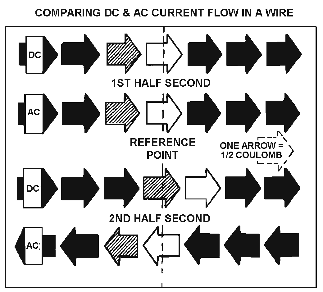
DISADVANTAGES OF DC COMPARED TO AC
� 6������ ��� � ��������� ���� � ������� ��� ���������� �������� ����������$������ ��� ������������
���� ���� ������������� �������� ������ ������������2������ ��� � �� ������������������ � ������$�����
�� ����� ������������������������ ��� �*� � ���������� ��+���#� ����������� �����-�������� �� ������� 7�
�� �� � �$������5� � �$������������������ ������ ����� 7��� ����2������7��� �� � �� ������������ ���������
��� ������ 7��� �����������$������ ������������������7��� �� � �� �������� ����� ����� ���� ���������7��� ��
� ���������������5������7��� ����6����������� ����� ����������������������� ����$����� ��������������
�#�� �������������� ���������� � �� ����������
� )�������� ������������������� ������������������ ����� ����� ��������������� �������������*2+���� �
����������� ������� ��� ������������ ������� ����� ������������� ���������������� ����6������ ���������$�
�� ������ �������������� �� ������������������ �������*0+��������� ����-��������� ���� ���#�� ����2�0��
,������$��� �� ���������������� ���������� ������������ ������� �������������� ��������������� ����� �����
��� ������� ����������� ��� ��-� �� ������������� �� ��� �� ���������������� ���� �������������� �� ��������
������� ����������������������������������������� ��� ����� ������8��������������� �������������� �����
�������� �� ��������� ���� ������������$������ �� ��� � �������� ��� � �� ���� ���������� ��� ���
�������������� ��� ������ ������ �����������*��+��
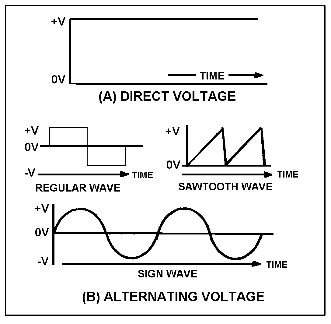
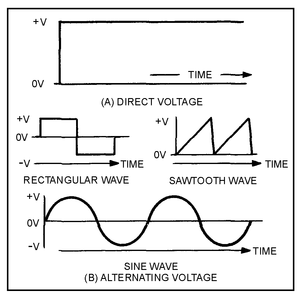
Figure 1-1.—Voltage waveforms: (A) Direct voltage; (B) Alternating voltage.
�
����
� �� '��� ������� �����$�� ������ ����� �������������������������������� ��� � ������������� ���
�� �����-0)1�9:0;/0��*-����������� ���� �����5� � ���� ����� ���� �� ��� ��+������������
�������� ������ ������ � ��������� �� ������� ���� �� ������������ ����� ������� �����)������� ���� �� �
���������� ��$������������� ���������������� ������ ����� ��������� ����������� ��� ���)����������� ���
���������������� �� ��� ���$������� ����� ���������������������������� ������������ �����#� �����������
�����<������ ��� ����������������������������� ��$�� ������ ������������������ ������ ������������� ��� �
������������ ��� � �������� ��� ��� �������� ���
Q3. What is a disadvantage of a direct-current system with respect to supply voltage?
Q4. What disadvantage of a direct current is due to the resistance of the transmission wires?
Q5. What kind of electrical current is used in most modern power distribution systems?
�
VOLTAGE WAVEFORMS
� 4�������'���������������������������������������������� ����$������ �$�� ������������������� ���������
� ������ ����������������� ������2���������� ������������������ �������� � ��������������� ����������������
��� �� ���������������� ��������������� �$� ��� �������� ��� ���������� ���)��-�������� ����� �����������
����������������� � �������� ���� �������������������� �� ���������� ��� � ����� '�������������� ��
� ���������� ���8��-������������� ������� ���������������������� ��� � ������ ��������������� ������
� ��������������������� ��'����������6)=/9:0;��9 ���������� ���8��������� ����������� ���
� ���� �� �������� ���:�������� ��������$������ ��������� ������� ��� ��� �����������
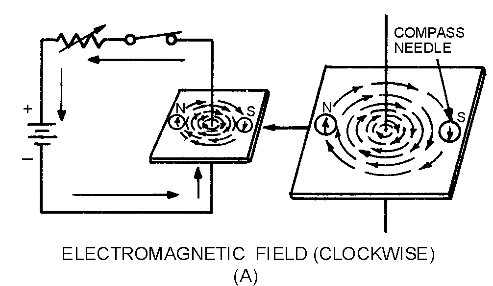
Figure 1-2.—Magnetic field around a current-carrying conductor.
�
�� �
ELECTROMAGNETISM
� -���� �������� ��������� ��� ���������� ���8� ����� ������������������ ������������ � ���������
� ���� ����) ����������������������� ��������������� ����� ���������$����� ��������������������� �� � ���
���� ����� ����� �� ����� ��� ���������������� �������� ������ ��� ������ �������
� -�������� ���� ������ ���������� ���� � �� ����������� ����� � ������� �������� ��;��� ���$�
�������� ����� � ������������������������� ���� � ��������� ���� �� �� ��� ������-� �� ��� ��� �� ���
������ ���� ����������������� ����� � ��-��� � ���� ���������� �����5� � ������������ ����� � � ��
���������������� ���� �������������$��������� �$������ ���� � ��� �������������� ����� � ��-� �������� �
���>��������� �� �������������������������/./&-0:;)31/-2�;��-�������� �������������� ���� � �������
����� �������� ���� ���� ��������� �� ���� ����������� ����� � ������ ���� � ����9����5� � �$�����
����'����������
• )��� ���� ����������� ���������������� ����� ���� ����� � ��
• -��� ������ �� ������� ��������������� �������� ���� ���� � ��� ��� ���� ����� � ��
• -������� �������� ������� ���� � �������������� ������ � ���� ������������ ����� �� �� ��������
�
MAGNETIC FIELDS
� 2���(�?�,����&�� �� ���:������$���<�� ������� � ��$����������������� � ����� �� ���� ���5 ������������
����� � ������ ���� � ����,��� ������������������ ���� ���������� ��� ��������� ��� ����������� ��
����� ����������������������������������������� � ��� �����
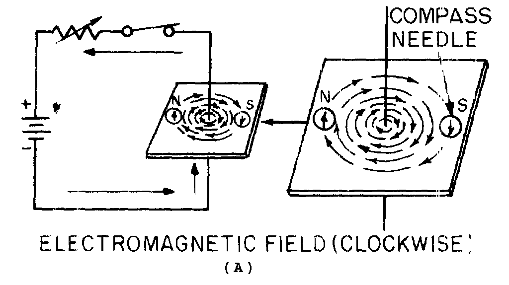
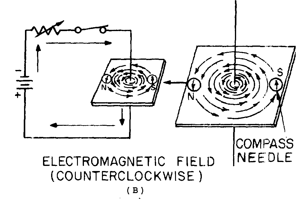
MAGNETIC FIELD AROUND A CURRENT-CARRYING CONDUCTOR
� 2������ ����� ��� ����� ������� � � ��������������������� ������������$������� ��������� ��� �� ���
��� ������ ������� �������������������$������ �� ��� ��������������������� ����� ���������4�������
�� ��������������������������� ������������� �������������� ���� ��������� ��� ����������2�������*)+�����
*8+��������� ����$���������� ���� �������� �� ������������������������ @���� �� ������������������4�������
����� �������� ���� ���������� ����� ������������������������������������ �� ������� ����������� ����
�� ���������������������������� ��������� ��������� ����� ��� ����-���� ���� ���������� ����� �������� ��
���� �������������� ���� ��� ���� ��������������� ����������� ������� �����
�
��!�
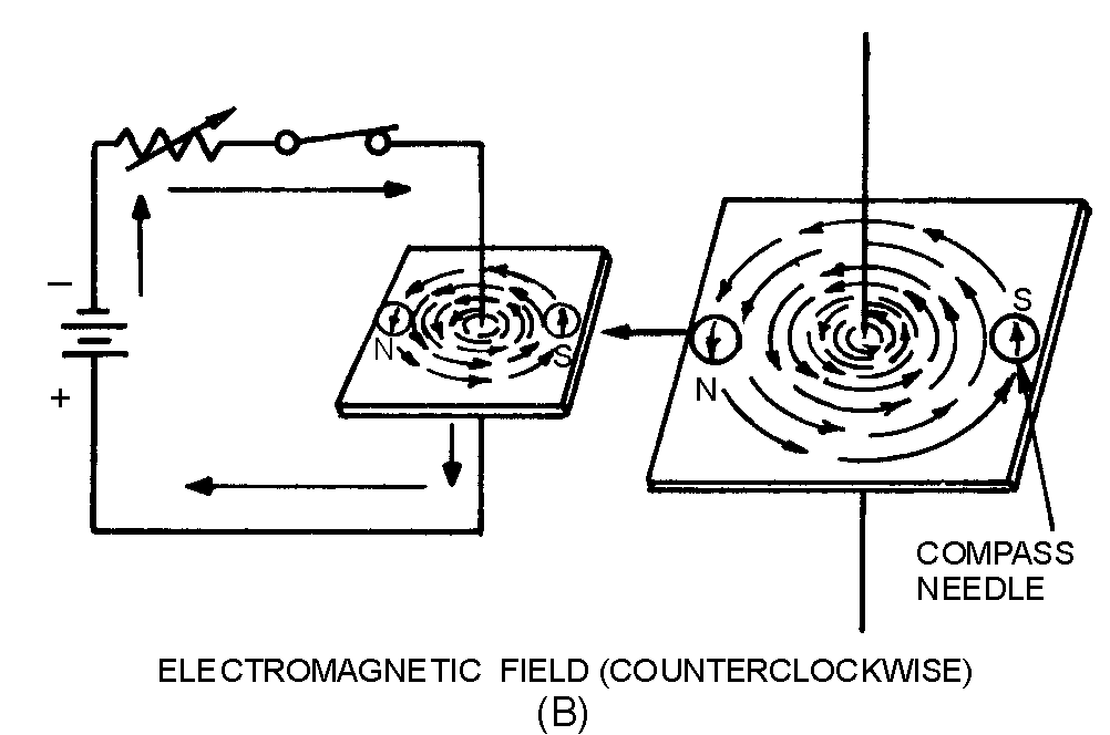
� 2��� ���������*)+$��������� ����� ��� ���������������� ����� ��� � ���5 ���� ��� ��� ������ ������������
�����������6����������������� �����������*����� ��������*)++$������ ���� ����������� � �� ��� ��'� ��$����
� �������� ����������,������$� �������������������� �� ��������������������������������������� ����
���������*����� ��������*8++$������ ���� ����������� � �� ���������� ��'� ����
� -����� �� ���������������� ���� ���������� ����� �� ����������������������������������������
� ���� ������� ���������������� ��� ���������������� ����������� ������� ������������./9-�,)1<�
0�./�9:0�)�&:1<�&-:0�� �������������������������� ������� ���������� ���������� ���5������� ��
����� ���� ����������� �������� ���*�������+�*−����A+$������� ������� ��� ��� ������� ���� ���������� ����� ��
��������������1������ ���� ���� ������ ����������1��������������� �������� ��� ������� ���� ������������������
�� ����������� ������� ��������� �� ��� ����� ������ ����� ��� � ���������� �������� ����
� )�������� �������� ������� ��� ���� �� �� ���� ����������������� ���� �������������� ���� ���������
� ���*����� ��������*)++��6����������������� ��������� ��� �������$��������� ���������������� ��������)�
���������� ��� �� ����������������������� ������� ������������������������������� �� ��������� ��� �����
���*8+��1�� ������������� ���� �������������� �� �� ��������������$���������� ��������������������������)�
��������������� ������� ������������������� �������������� �� ��������� ��� ��������*&+��1�������������
� ���� �������������� �� �� ����������������$���������� ��������� ���������������) ����������������� ����� ��
� � ������������������������ ������������� ��������� �� �������������������$�������������� ����� �� �������
�����������#�� �� ����� �������������������������
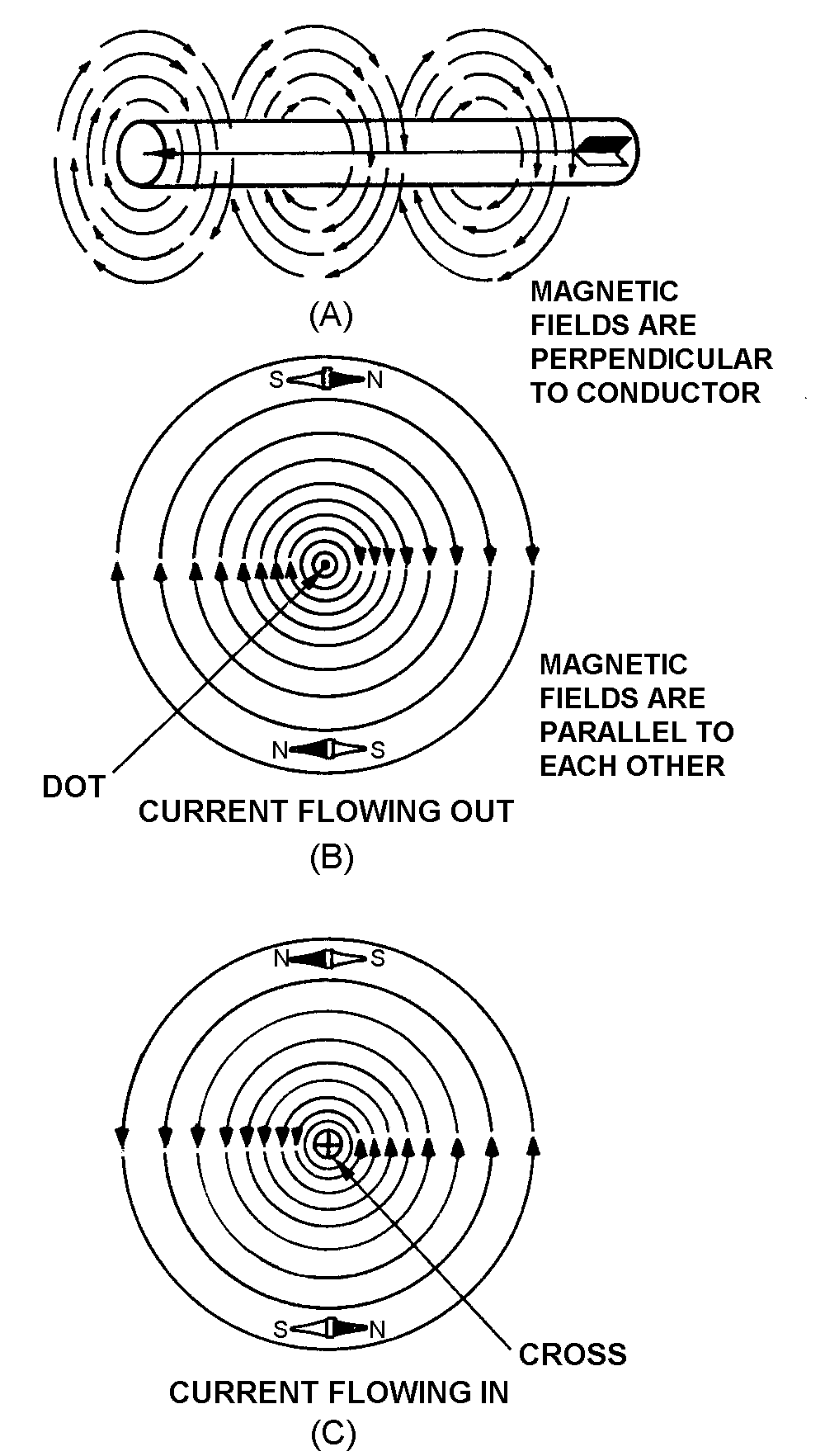
Figure 1-3.—Magnetic field around a current-carrying conductor, detailed view.
�
��"�
� 6����������>���������� � ��������������������� ����������� �������� ��� ���� ��$����� ����� �� ����
����������� � ������� ����������������������������� � �����������������������$���������� ��� ������� *)+��
-������� � ����������������� ������������ ������� ���� ���� �������������� ��� ������� *8+��1�������������
� � ����������������������� ������� ��� ��� ���� ����������� � ������������������������������-������� � ���
������������������������������� ������������������������� ���$����������� �������� � ��������������
�����������-� �� ���������� ���������� � �������>�������������������������� ������������ �������� ��
� ���� ��$������ � ����������������������������� ��������������&������� �$� �������������������������
����� ������������ ������� ���� ���� ���$������ � ���������������������������� �������������
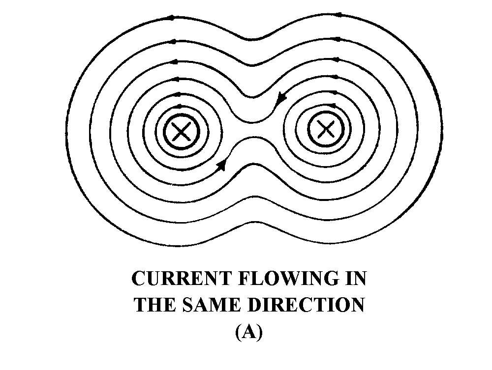
Figure 1-4.—Magnetic field around two parallel conductors.
�
��%�
Q6. When placed in the vicinity of a current-carrying conductor, the needle of a compass becomes aligned at what angle to the conductor?
Q7. What is the direction of the magnetic field around a vertical conductor when (a) the current flows upward and (b) the current flows downward.
Q8. The "left-hand rule" for a conductor is used for what purpose
Q9. In what direction will the compass needle point when the compass is placed in the magnetic field surrounding a wire?
Q10. When two adjacent parallel wires carry current in the same direction, the magnetic field about one wire has what effect on the magnetic field about the other conductor?
Q11.When two adjacent parallel conductors carry current in opposite directions, the magnetic field about one conductor has what effect on the magnetic field about the other conductor?
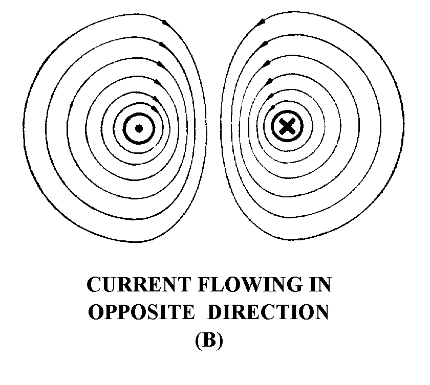
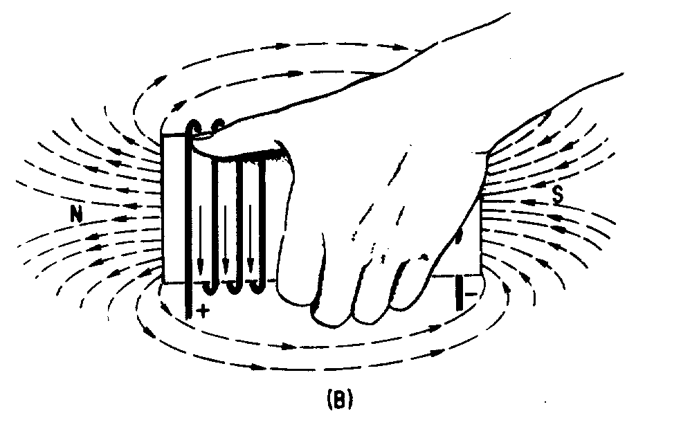
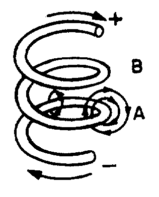
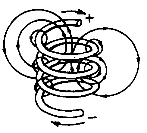
MAGNETIC FIELD OF A COIL
� 9 ��������*)+� ������������������ ����� ��� � ������������������������ ���� ����5 �������� ��� ����
� ��������� ����9 �������!� ������������������������� ����� ��� ���������������������$� ����� ������ �����
��������� ����� ��� � ��������������������� ������ ���������������9 �������!*)+� ������� �������� � �
��������� ������� ���������������� ��������� � ���� ��9 �������!*8+������������������� ��� �� ������
������ ���� ��1�� ������������������������������ ����� ���� � ������B�����4��
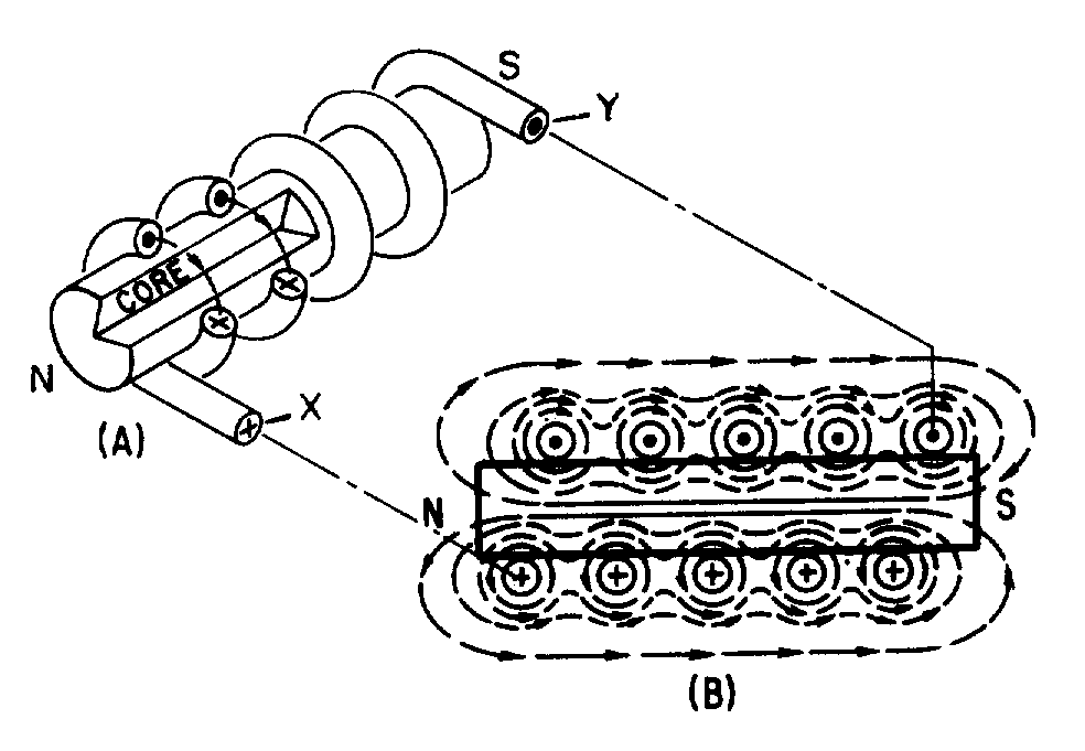
Figure 1-5.—Magnetic field produced by a current-carrying coil.
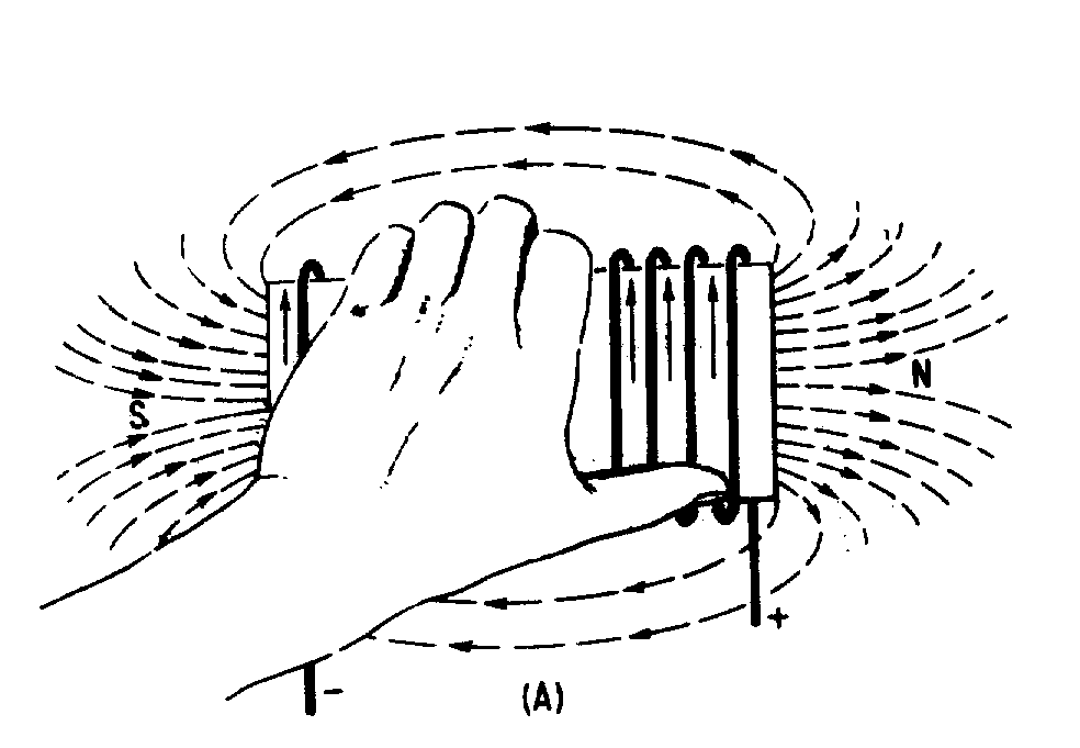
Figure 1-6.—Left-hand rule for coils.
�
��(�
� 6������������ ����������������������� $����� ����� ��� � ���������������������� ��� �'��� �������
� � ������������>�������������*����� ������� *)++��-����� � ���� �� ���������� ��������������������������
�� ��� � ��� ����������������� � ������ �������:���������������� � ������������ �������������������� ����
�������� ���
Polarity of an Electromagnetic Coil
� 9 ������������������������� ���� ���������� ����� ��� � ��������������� ����� ������������������
� ���� �������������� �������� ����-���$���������� ������������ ����� ������������������� � ������� ���� ������
���� ����� ��� � ������� ������������2���� ������������������ ���������������� ������ �� ������������������� �
������������� �� ����� ��� � �������������� ��
� 6��������� ���� ������������������ ������ � ��'����$�������������� ������� ����� ���� �� ����������
�� ������ �������./9-�,)1<�0�./�9:0�&:2.���-� ���� �$� ��������� ��� �������"$� ������������
�� �����
� 3����������� � ������� ��������$�� ��������� ����������������������� ������� ���� ����������� �������
��������� ����4������� ��� �������� ���������������������� ����������� ��
�
��?�
Strength of an Electromagnetic Field
� -��������������� ����� ���������� C�� ����� ��� � ����������������� ����������������-��� � �������
���� ������� �������� ����� ����������� �� ������
• -����� ����������������� ��� �������� ��
• -���� ����������������� �� ��� �������� ��
• -������ ����������� � ��������������� �� �����
• -����������� ���� � � ������������
Losses in an Electromagnetic Field
� 6������������� ���� �������������$�������� �� ����������������� � ������ ������� � ���� ���� ��$�
������ ����� ����� ��� � ���6��������� ���� �������������������������$������ ���� ������������� �C�
� �� ����� ����������$����� ������� ����� ��� � ������������� ���� ����-����������� �������� ����#� ����
���������������5������$������� �������� �� �����-� �� �������������* ��������� ��������+� ���� ���
,4�-/0/�2��.:����,������� �� ���� ���� ������� �����#� � ���D��������$� ����������������� � ��
�5����� �� �����$�����������$������������� �����6������������� ��������� �������� ����� ���� �� ��� �$�
�������� �� ����� ������������ �� �������� ��
Q12. What is the shape of the magnetic field that exists around (a) a straight conductor and (b) a coil?
Q13. What happens to the two-pole field of a coil when the current through the coil is reversed?
Q14. What rule is used to determine the polarity of a coil when the direction of the electron current flow in the coil is known?
Q15. State the rule whose purpose is described in Q14.
BASIC AC GENERATION
� 9�� ��������� ����� ����� ������� ��������������������������� ������������������������ ����� ��
� � ��������� ��� ���2�� ��� ���$������������� ������� �����*� �+��� ��� ����� � $����� �������������
����� ��� ����� ��� � ��������������� �� ���������������-���� �$� �������������� ��� ����� ���� ����� ��
� � �$������ ���������� � ������������������� ����$����� �� �� ������� �����������������-� ��������� ���� ���
� ����� ����� �� ����� ����
CYCLE
� 9 ��������%�������(������������������ �������� ���*���������+��� �����������* ����+� ����� ��'� ���
� ���� ��������������� ����� ��� � ���������������� ����������� ������ �������9������������5� ���� ��$�
���� �������������� � ���� ���������'��� ������ ������ ���1�� ��� ��*)+��������� �����������������'��� �� ��
�� ���� ����*���� � ���+����� ��������������&����#���� �$� �� ������ ���1:� ��������������-����� �� ��
������������ ������ �$��� ��� �� �� ��� ����������� ���� ���� ����� ��������������������������� ������ ����
��������$����� �� �� ��������)������ �������������������������� � ��������� ��*8+$� ������� �������� ����
������������������������* ���� ����������� ������ ����� ����+��������� �� ������ ��� ����� ���� ���������
����� � ��* ������������+��)��*8+$��������������� ���������� � �� �������#�������������� � �������� �� ��$�
���?7E $�������� � ����� �� ���8��������������������� ���������� ���� ���� �������������� � �$������� �����
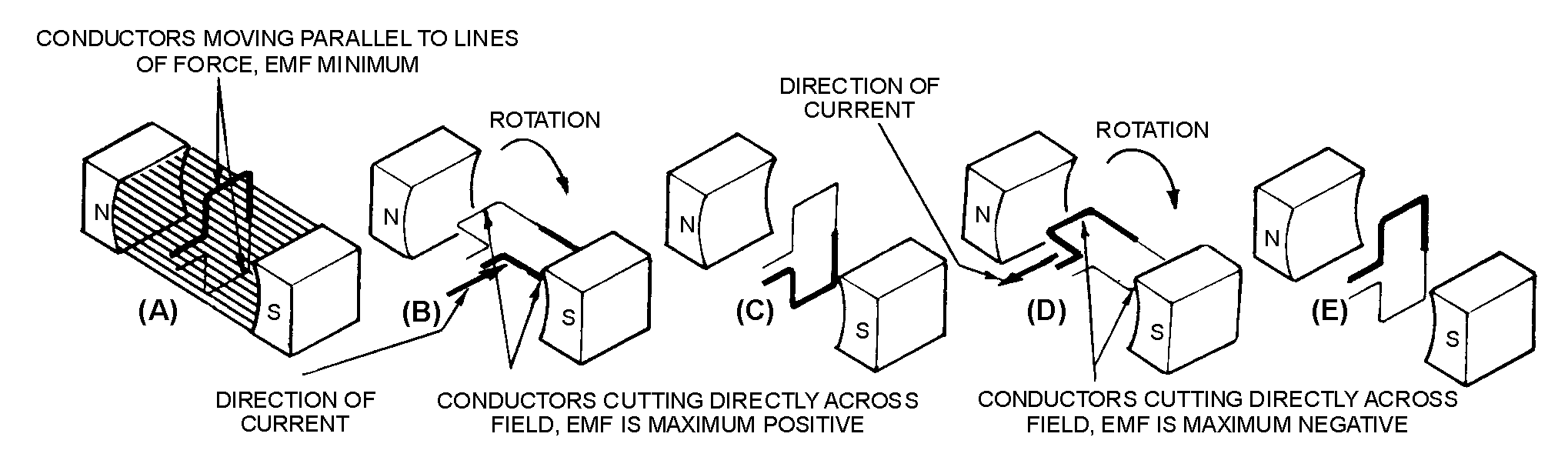
Figure 1-7.—Simple alternating-current generator.
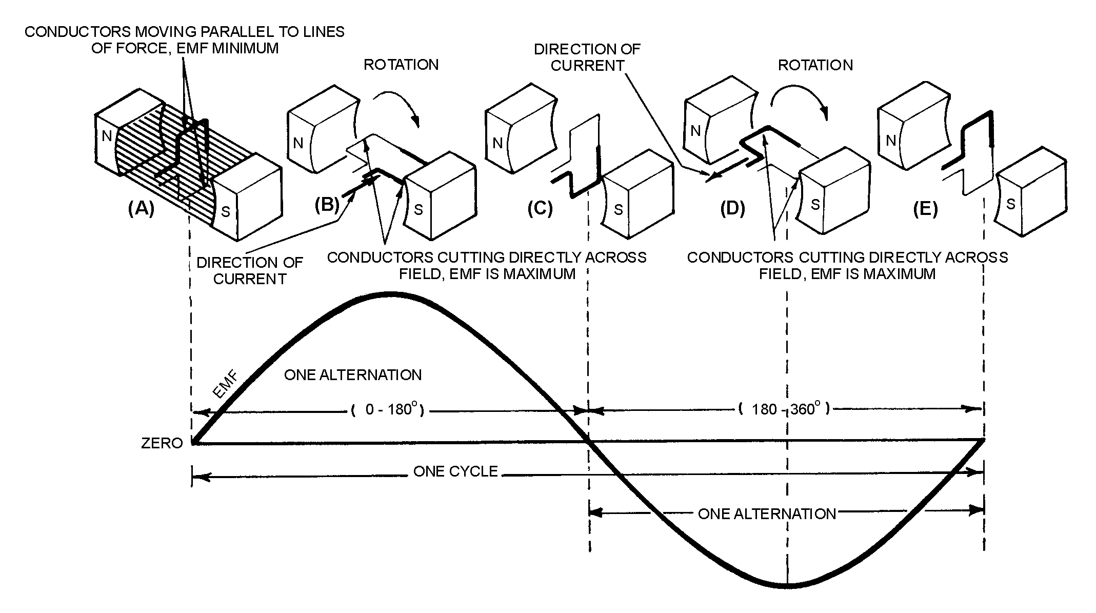
Figure 1-8.—Basic alternating-current generator.
�
���7�
������� ���������������� �� �5 � ��6���������� ������ ��������� ����������� ������ ������� �������
����� ������ �*)+����*8+� ��� �����������������*���������� �������������+$���������������������������� ����
� )������ �������� ��������������������������������� � ����������� ��� ��*&+$� �����������������������
��������������-��� ��������� ������������������ � ������'��� ����/������ �$����� ���� ���������� ��
�� ��� ����� �������� � �������� ����� ��� � �$��������� �� �� ������� �����������������
� -��� ����������������������������������� ����� �� ��*����� ������ �������(7E +��2������������ ���
#���������� �� ��� �����$� ��������������������� ����
� 6���������� ������������ ����� ������������������� ���������� ���*�(7E ����������"7E +$�����������
������������������� ����1�� ��������� ��� ��������� �� �������� �� ���������� ��������� ������6�����
���� ��� �������� �� ���������� � ��$� �� ����������� ����
� -���� ��������������������� ������ ��������� ������������� ����������� ����� �������� ���������� �����
1�� ���������� ������������� ����"7E�$��������� ������ �����-6:�).-/01)-2:1������������:1/�
�� � ����&4&./��������� ����
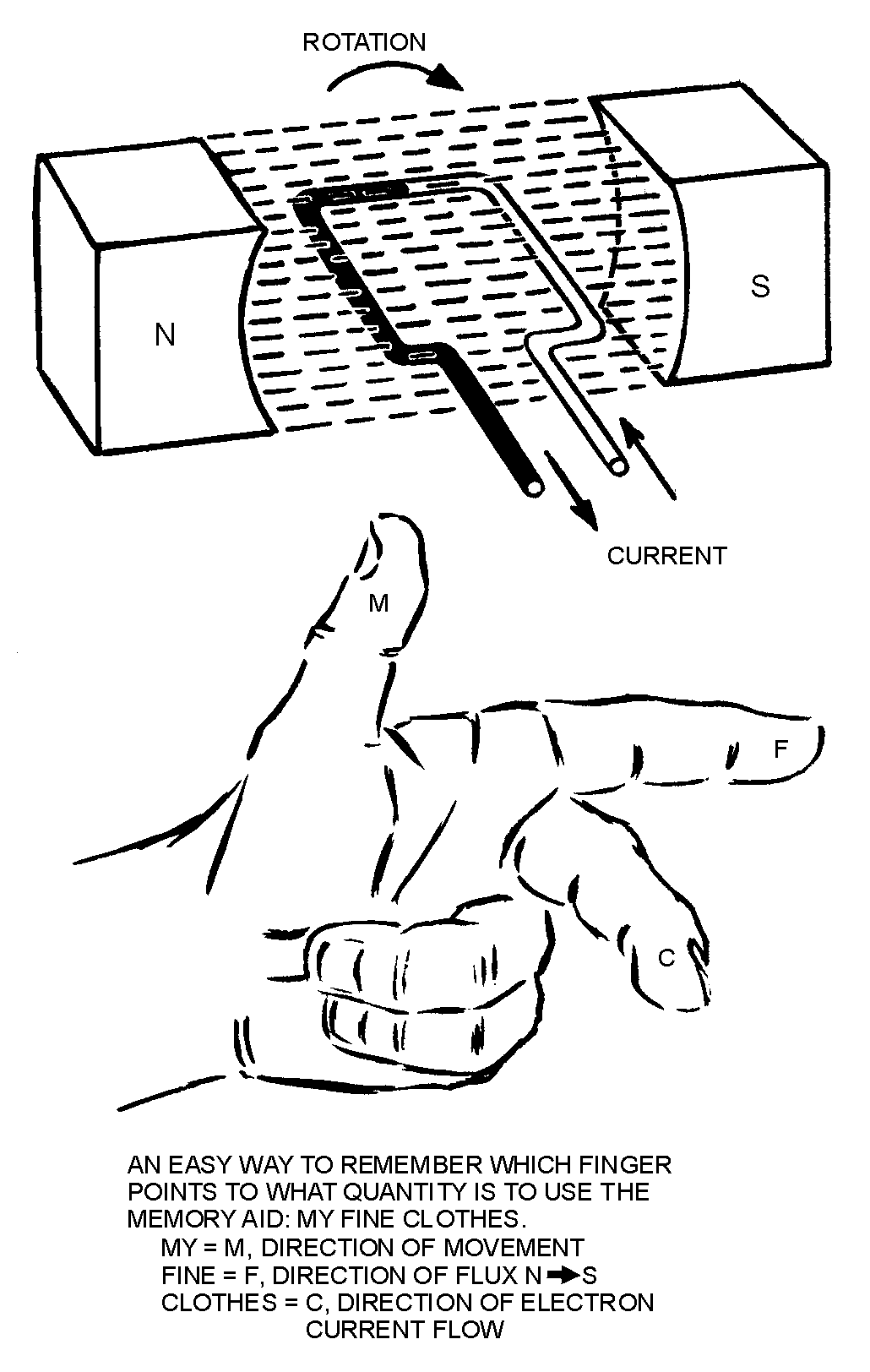
Figure 1-9.—Left-hand rule for generators.
�
�����
� )��� ������ ���������� ������ ������������������������������������� ���$�������������� �������
� ���� �������������� ������ ��������� �������./9-�,)1<�0�./�9:0�3/1/0)-:0���0��������� �����
��?��-��� ����������� �� ����� �������� �����9 ���$�� ��������� ���������������� ������ ���� �������� ������
����������4����-,�;8�� ������� ��� ������� ���� ����������� ���*�� �� ��� ��� ������������ ����������
����� ��� � �+D������9:0/9213/0�� ��� ��� ������� ���� ������ ����� ��� �5�*��������������+D�����
�����;2<<./�9213/0�*�� �� �������������������+�� ��� ��� ������� ���� ������� ���������������� ����
� 8����� � ������� ����������� ������������'��� ��������� ���� ��*8+� ��� �������($������ �� ������������
��������� ���� ������� ���� ��� �� ��������������������������� �� �$������ ������� ����������� ���������
������ ��������� ���$������ �� ��������������������� ��� ���� ����������� ���� ���� ����-������� �������
�� ������ ������ ����������������������� ��������� �� ���2�� ���� ��� ���� ���������������������� ������ �����
� 6�������� ���������������������� � ��������� ��*<+����� �������($�������� �������������-������'��� �� ��
�� ������ ��������������$��������� ������ �� �� �� �������� ��������������8����� � ������� ���������
�� ���������� �$������ ������������������ � �������� ������ ������� � �������������������������� ���� ����
-����� ������� ��������� �5 � � ���� ������� ���� ��$������������������ ��������� ��� �������(��-���
����� �� ������������� ����� � �� ���� � ���*/+$������ ����� ����� ����� ����� ��@�����-���� ���������
����������������� � ������� ������� ��������������������������� ��� �����) ����� ������ ��������� ���� ��
������������������ ��� ���� �� ��� ����� ��'� ���� ���� ����2������� ������ ��$����� ����������� �����
� ��'� �������������� ��'� ����0����� ������������ ���� ������ ��� ���$����� ����������� ����� ����
� 2������ ���� �������������������"7E �����������������$����� ���������������������� ����� ��� � �� ��
�� ��� $������� �������������� ����� ������������� ����$���� �� ������ ��� �������?��&��� ����������� ������
���� ����� �������������� ������� ���������� �������� �����$� �������������$��������� ������
�
�����
� )�� ��� ��������� ��� �$�������� ������ ������������� � ����� ������ ���� ������� ������� ���
0����� ������,/0-F�*,@+������������� ���������� �� ������������ ��������������2��:1/�&4&./�G/0�
�/&:1<� ��:1/�,/0-F$�������77���� �������������������#�� �����77�����@$������������-��������������
1//-�$�������� ���� �� ������������������� � ��� ��� � ���� �� ��� ���$������������ �����@�*,@+� �������
���������� ��� � ���� �� �������� �����������
Q16. When a conductor is rotated in a magnetic field, at what points in the cycle is emf (a) at maximum amplitude and (b) at minimum amplitude?
Q17. One cycle is equal to how many degrees of rotation of a conductor in a magnetic field?
Q18. State the left-hand rule used to determine the direction of current in a generator.
Q19. How is an ac voltage produced by an ac generator?
FREQUENCY
� 2������ ���� ������� �������(�*)+� �'��������� � �������� �� ��������������$������������������������
������ � ������� ����������� ���������������*��,@+��2������ ��������� ����������� �� ���������������
�������� ��������������� � ������� ��������������������*��,@+��-����� ��������� � ������� ������
� ������ ���������������� ������� � ����������������� ���������������������90/H�/1&4��9��#������ ��
� ����� �������������5�������� ������@��
� ) ������ ��������������#������ ����� ����������� ���������������� ���� �������� ���� �� ��#� � �����
��#� ��������� � �����#����������������������� ����
Q20. Define Frequency.
PERIOD
� )�� �� � ��� ���� ���������� ������������������������ � ���� ��������-2;/��1�� ��������� ��������7�
����������� ��������� ���������� ������������#���������������@�*,@+��� ��������� ��������������������$���
��� �� ������#� ��������� ������������� ���-���� ����#� ��������� � ����������� �������������� � ��
�� �������G/02:<��������������2��� ��������7$�������� ��� �������� ����������-����� �� ���� ����������
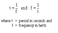
� ��*�+��������#������*�+� �� �� ���������������� � ���
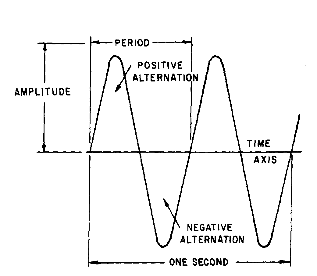
Figure 1-10.—Period of a sine wave.
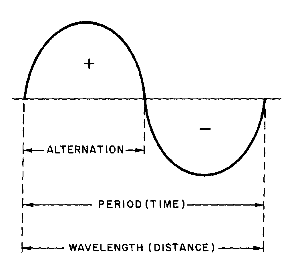
Figure 1-11.—Wavelength.
�
�����
� /������� ���������� �������������� ��� ��������7����� ����������� ���� �� ������������ �� ���� ��
�� ������-������ �� ����� ������������� �������� �������� ����� ����� � ��� ���� �������G:�2-2=/�
).-/01)-2:1��-������ �� ����� ������������� �������� �������� ����� ������� ��� ���� �������
1/3)-2=/�).-/01)-2:1��2����� �������$������������ ������ �������� ���� �� � ��� @�����������$�����
����� ��� ���� �� ����
� -���� ���������� �@����������� �5 � ��� ������������ ������ ��� ���� �������);G.2-�</��-���
� � ��������������� � ���� ������ ������������ � ����������������� ���� ������ ������������� ���
WAVELENGTH
� -���� �� ����'���������� ������������� � ����������� �� ����� �������������� ����������������� ��-���
� ������������ ����������� ����������� ����� ����� ��� �����������������6)=/./13-,��6��� �����$�
�� ��������������� �� ���*3���'� � ���+$� ������� �������� ��������������� ���� ������� ������������ ��
�� ������������5����� ���4����������������� ���� �� ���� ������5� � ���� �����������-����� ����������
������� ������ ������ ����������� ��������� ��� ������ ����������� ������������ ������� �� �����������
������ ���� ������������5����� ��*����� ���������+��
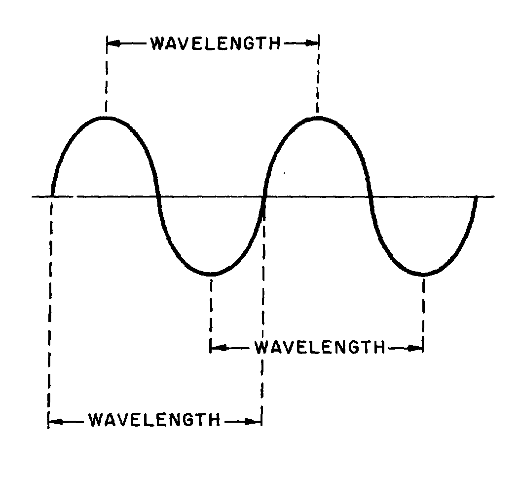
Figure 1-12.—Wavelength measurement.
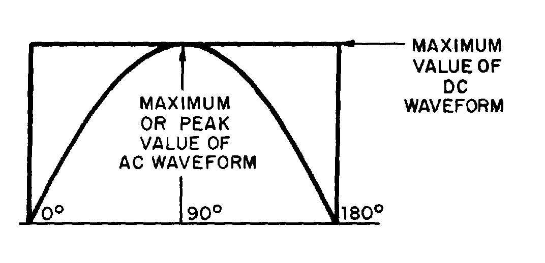
Figure 1-13.—Maximum or peak value.
�
��� �
Q21. What term is used to indicate the time of one complete cycle of a waveform?
Q22. What is a positive alternation?
Q23. 6�������������� ��������������� ������������ �������� ������$�������� �� �I�
�
ALTERNATING CURRENT VALUES
� 2��� ����� ���� ������ ����������������� ����$������ �������� ��� ����������������5������������������
������ ����� ����� �����;)B2;�;����G/)J��� ���$�G/)J����G/)J��� ���$�/99/&-2=/��� ���$�
)=/0)3/��� ���$����21�-)1-)1/:����� �����/��������������� ����������� �������� ��� ������� ��
������������� ������ ��������� ��������������������� ������
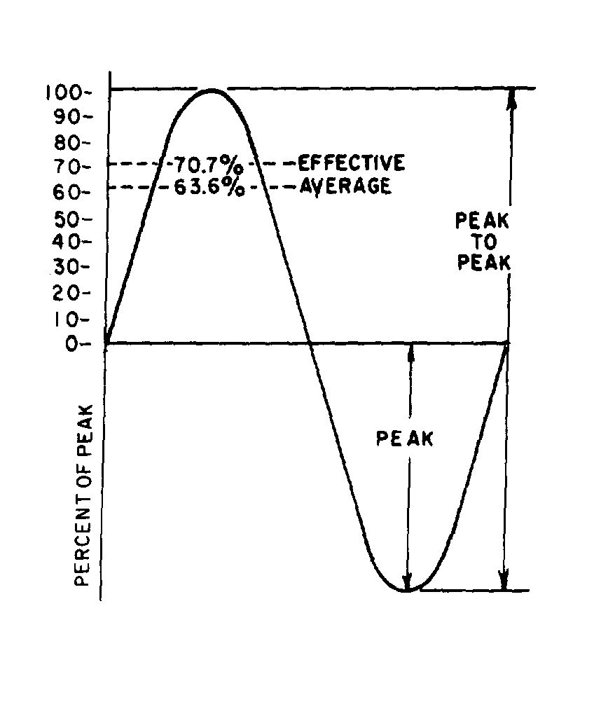
PEAK AND PEAK-TO-PEAK VALUES
� 0��������� �����������1�� ��� ��������������� � ���� ������ ��������� ��������*���� ����� �������+�������
���������� ������������� � ������� ���1������������������������������������������ �� � ����������������
��� � ���� ������ ��$���������������������� ��� ������������ �� �5 � ��� ����,������$���������� ����
������������������������������� �������� �������� ��� �����5����������� �������� ���������� � ���� ������ ���
��������������� ��� �5 � ��� ����)���� ���� ������������������� ���������#�� ��-� ���� ����������� ���
����� ��������������������� �5 � �������'��� ����
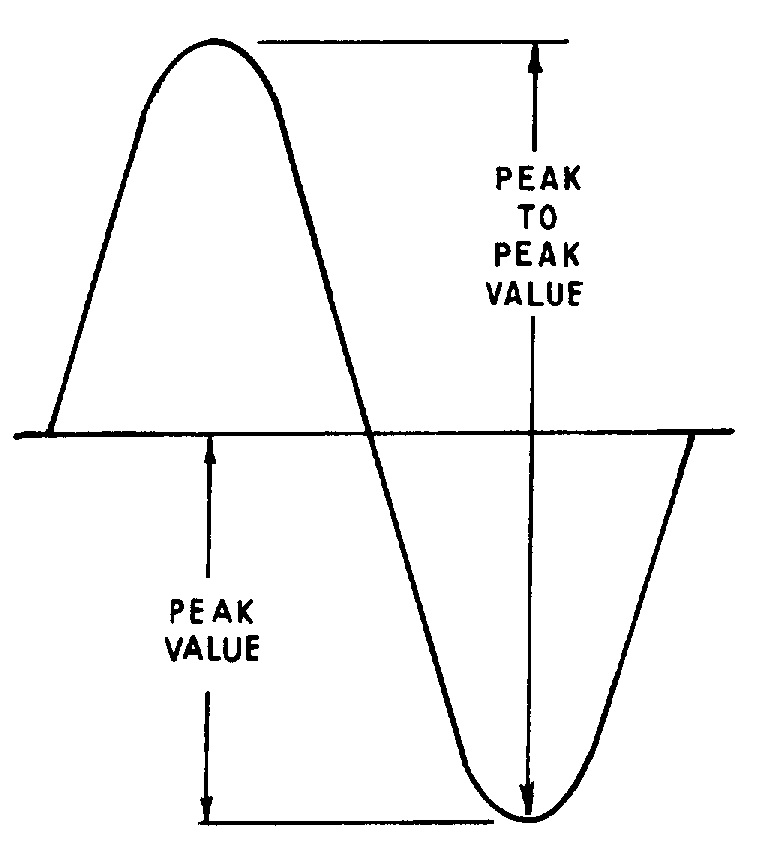
Figure 1-14.—Peak and peak-to-peak values.
�
���!�
� <�� ���������� � ������� ������������������� ��������� �5 � �������'��� ���$���������������� � ���
�� ����� ����������������������������� ����� ����� ���-���� ������������������������'���� � ����� �������
�������'������ ����� ��� ���� ����������'�������'��� ����������� ���������-� ���� ��� ���� �������
�5 � �������'��� ����������� ������������ ���� �� ������������ ������ ������������ �������1��������
� ��������������������'��������'�������'��� ���� ��� �������� ������ ��� ������ ����� �����������������
�����5�������� ��/99/&-2=/�=).�/��*����� ������ ������� ����+������������� �����'�������'��� �����
Q24. What is meant by peak and peak-to-peak values of ac?
Q25. How many times is the maximum or peak value of emf or current reached during one cycle of ac?
INSTANTANEOUS VALUE
� -���21�-)1-)1/:����� ���������� ������ ����� ���������������� �������� �������� ����������������
����������� �� ��� ��������-����� ��� ������@���� ���������� �� ��� ������� ������� �� ��������� ������� ���
������ �� ������������ ����� ������� ����2�� ���� ������������ ������������'��� ��$� �������� ������ ������� ��
����� �� ��������� ������� ��������� ���������������������� ������ ��������������������� ����-���������
����� ����� �� � ����� ������� ��������������� ������������@���������������'��� ����
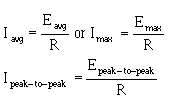
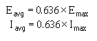
AVERAGE VALUE
� -���)=/0)3/��� ���������� ������ ���������������� ����� �����������������)..�����
21�-)1-)1/:����� ������� ���:1/�� ������ ����� ���������� ����� ������������ �@����������'��� ���
�����������������'����@������� �������� ������ ��$��������������� ��� ��������� ���� �����������������
���� ����4������ ������� ����������������� ��������� ����������������� ������ ��������������� �������
����� ������ ���*��������7E ������(7E +$����������� � � ��������� ���������� ������� ��������������� ����
������-����� ����� ������ ����������������� ������ ��������� ������������������������� ����#�� ����
7�"�"�� ����������'��� ����-������ � ���������������� ����� ��
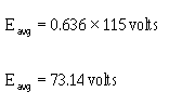
Eavg = 0.636 × Emax
������/���� ���������������� ������������� ������ ��$�����/ �5� ������ �5 � �������'��� ������� �� �$�
������� � ���������������������� ��
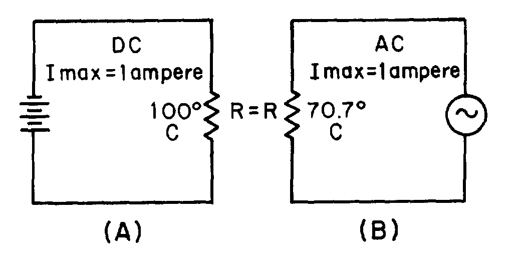
Figure 1-15.—Heating effect of ac and dc.
�
���"�
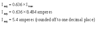
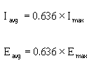
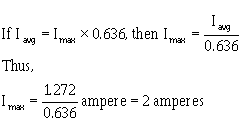
Iavg = 0.636 × Imax
������2���� ���������������������� ������� ������ ��$�����2 �5� ������ �5 � �������'����������
� <��������������������������� � � ������������������� ���� ������������������������� ���������� � ����
��� ���8������������� ����� ����� � ������ �������� ������ ������������ ������ �������������� ������ ��$�����
���������� ������������ ������� ���������� ������ ��������� � ������� �� ��@�����
Q26. If any point on a sine wave is selected at random and the value of the current or voltage is measured at that one particular moment, what value is being measured?
Q27. What value of current or voltage is computed by averaging all of the instantaneous values during the negative alternation of a sine wave?
Q28. What is the average value of all of the instantaneous currents or voltages occurring during one complete cycle of a sine wave?
Q29. What mathematical formulas are used to find the average value of current and average value of voltage of a sine wave?
Q30. If Emax is 115 volts, what is Eavg?
Q31. If Iavg is 1.272 ampere, what is Imax?
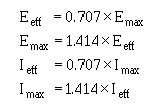
EFFECTIVE VALUE OF A SINE WAVE
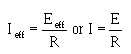
� / �5$�/���$�2� �5$�����2���������� ��������� ����� ������ ������)��������� �������� ������/99/&-2=/�
�� ���������-� �� �������� ������� ������ ����� ���������������������� ������������ ����������������� �������
������� ����� ���� ������� ������� ����������������� ��������������� ����� ��������
� 2�������� ���� ����� �������������� ��������������������� ���� ������� ������$������ ������������6����
� �������������� ���� ������� ������$������ ��������� ���� �� ����������������� ����������#�� ��2�0��������
,������$�� �������� ������ �������������� ����� �5 � ��� ��������� �������������� � ��� �������������
�� ��$������ ������ ������������ ���������������� ��������� ��������� ����������� ���� ������������������
� ������
� 9 ��������!��� �������������� ���������������� ���������������������� ���������������� ������������
�
���%�
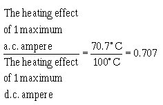
� /5� ���� ����)�����8����� ��������!�������� �����������������*%7�%E &+���������������� ��������
� ������ �����������*����� �$�������� ����� �5 � ��� ��������� ����+� ���� ��%7�%���������������������
*�77E�&+���������������� ��������� ��������������;���� �� �� �$�
-��������$����������� ����� ���������*2����+�K�7�%7%��2 �5��
� -������������� �������� ����������� ������� ���������� ���������� ������� ����������� �� ������
������ ����� ������� ������ ����������$����� ��'����������������� ����������� �������)��� ������ �����������
���� ������������������� ����� ����������� ���������� ���������������� ����� ������� ���������������� ��
������������������ ��������� ��������������
� 4��������� ��������������� ����� ��������� �������������������������� ��������������������������' ���
�#�� ��������� ��������������� ���������������� �������������������5����� ��������#�����������������
����������������� ���������#�������� �����
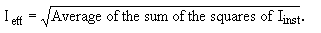
� 9����� ��������$����������� ����� ��� ���������� ������������� �����#������*� �+��� ����-���$�
� ������������������$����������� ������� ���� ���*2���+������� ������������������� ��7�%7%�� �������
�5 � ��� ��������������*2 �5+��-���$�2�����K�7�%7%��2 �5��6����2����� ��'����$���������� ���2 �5������ ��� ������� � ��2 �5�K��� � ��2�����4��� �������������������������������� � ��� ������ ��-��� ������$� �5� ���� ��������!���� ����������������� �� ����5� ���� ����)��� �������������� ��� ��������!*)+� ��
� ��� ���������� ���������������� ������� �������������77E�&��) ������� �������������� ��� ��������!*8+�
�� ������������ ������� ������������������� ����� ���77E �&��)���� ���� ��� �� ��������������� �5 � ����
�� �������� � �� ������ ����#� ���� ���������������������� ������ �������������� ��������������-��������$� ��
�������� ��� ������ �5 � �����������#� ���� ���� � �� ������������� ������������2�� �� �������������������
�� � ���������������� �� ���� ��������������������� ����� ���*2����+��������� ������������������� ��� �����
7�%7%�� ������� �5 � ��� ���*2 �5+��
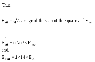
� � ����� ������ ����������� ���������������� ������ ����� ����$�������� ��������������� ����� ������
�� ������������ �5 � ��� �������� ����� �������� ������������ ��������������� ����� ���������������������
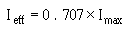
�5 � ��� ���������������������������������$����������� ������� ���� ���*/����+������� ������������� �����
��7�%7%�� ������� �5 � ��� �������� �����*/ �5+$�
�
���(�
� 6�������� ������ ���������������� ������� ��� ������ � ��� �������'���������� ���� $������� ��� �����
������ ����� ����� ���������� ������� � �������� ���������������������0� � ���������� � �����$��� ����
��'������������������$������� ���������� �� ����������� ����� ��������������������� ������
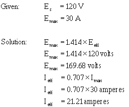
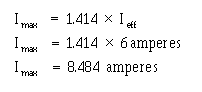
� G��� � ��)�� ��� �� ��'����������������� ������ ����� ����������7��� ������������'���� �5 � �
������������7�� �������6���������������'��� ��������������� ������������� ���I�
�
� 9 ��������"������������� �� ���� ����������������� ������ ������������ �� ������ ��������� � ������
0�� ��������� ���� ������� ������������������������������������������ ��� �� �������
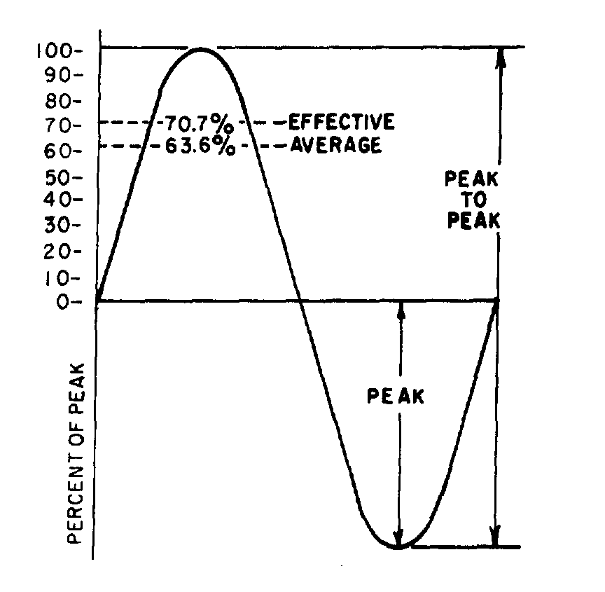
Figure 1-16.—Various values used to indicate sine-wave amplitude.
�
���?�
Q32. What is the most convenient basis for comparing alternating and direct voltages and currents?
Q33. What value of ac is used as a comparison to dc?
Q34. What is the formula for finding the effective value of an alternating current?
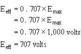
Q35. If the peak value of a sine wave is 1,000 volts, what is the effective (Eeff) value?
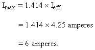
Q36. If Ieff = 4.25 ampere, what is Imax?
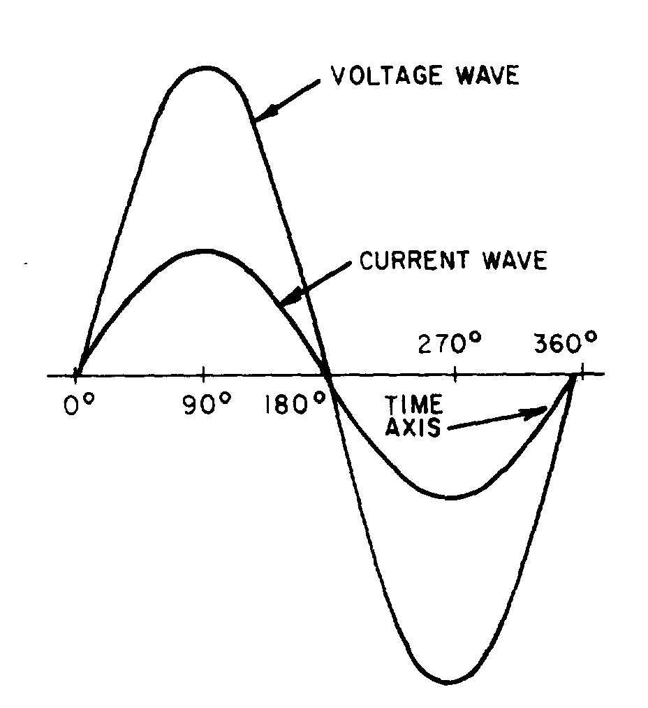
SINE WAVES IN PHASE
� 6������� ������������� ����� ����� ����������� ������$��������� � ����������� ��� ������ ���������-� ��
�� ����:� C�� ����� ����������������������� ��� ���� ��������� ��� ����������� ����� ������1����5� ���
� ��������%��1�� ������������� ������������� ����������������� � ���� ���������������������������� ������
��������� ��� ���5 ���1�� ���� ����������������� ����� ��������� ������� � ���� ���� ��$�������������
���������� ����� ��� �$��������������������� ��������������� ���� ��$�������������� ������������� ���� ����
6��������� ��������$������������������������������� ��������%$��������� �� �� �������� ��������������$�
����������� ��������21�G,)�/��-����� �������$���������� ��������� ������������������ �� �5 � �����
� � ��� ������������� ��� ������ �������� ��� ���� ����
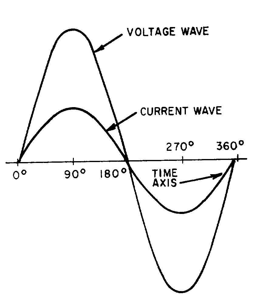
Figure 1-17.—Voltage and current waves in phase.
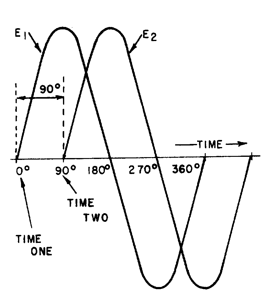
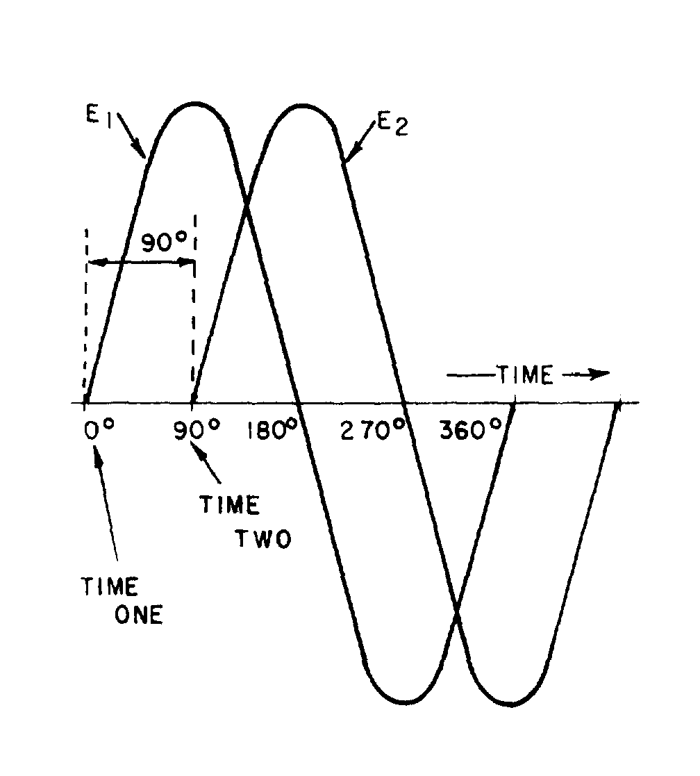
Figure 1-18.—Voltage waves 90º
�
���7�
� 2���� ��� ��� ��$������� �� ���������������� ��������� ���������������-���$� �� ������ � ��������������
��� ������ ����������� ��������� ������������������� ������ ��������� �������� ��� �����������
SINE WAVES OUT OF PHASE
� 9 ��������(��������� ����������/����� ��� ������ ������������������7E �*� �����+��)���� ����������/��
�������� ������ � ������'$��� ����������/���������� ���� ���*� �����+��� ������������ ���������������������
����������� �� �5 � ����� � � ��� ������������� �� ����������� �$���G,)�/�<299/0/1&/��5 ����
�����������������������-������������������� ��������:�-�:9�G,)�/��9����������������� ��� ��������(�
����������� ��������� ��?7E ��
�
out of phase.
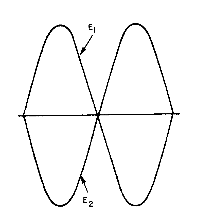
Figure 1-19.—Voltage waves 180º
�
�����
� -��������������� ��������������� �� ���� ��������������� ��������$�������� ��./)<�����.)3�����
������-���� ���������� �������� �������� �������� ������������� �������� �� �������� �����������0�����
��� ������ ��������(��:�����������������/���������?7E � ����� ��� �����������������/���4�������� ���
����� ����� ���� �� ���� �������� �������������/�� ����������/������?7E $��������������/�� ���������/������
?7E ��*/ ���������� ���� ���������D� �� �������������� �� ���� ������������������� �������������� ��
��������+�
� 2�� ������ � ����������� ����������� ������� ������������ ����������������� ��������������$��5�����7E �
����"7E ��6�������� ���������� � ����5 ���$��������������������� �������� ���������-���$������ ���������
������ ����� ����������� !E ���������� ���������������� �������������$�������������� ��������������� ����� ��
����������"7E ��������� ������������ ��������� ���������������
� )��������� �� ���� ������� ��#� ����� ��� �������� ��� ��������?��1�� ����������������������
���������� ����� ������������(7E ��1�� ���� ��������� ��������������������������������� �� �5 � �����
� � ��� ������������� ��� �$���� �� ��������������� ����������� ������������� ����� �� ����2������
������������5 ���������������� ���� ������$�����������������������#�� �� � ����$����������� ������
�������6��������������� ��������� � �����$��������� �������������������� ���� �� ���������� �����������
������������ � ������#�� ��������� ���������������������� � ������������������������
out of phase.
� -������� �������������� ���������������������� ��������$� ������������ ������������ ���5 ��������
������������������������� ���5 ������� ��� �������� ��� ���� ����-����� ���������������������������
����� ����� ���� ������������� ����������-��������������������������5 ��������� ������ ��*�������� �����������
� ���5 �+� ���� ����� �������������������
Q37. When are the voltage wave and the current wave in a circuit considered to be in phase?
Q38. When are two voltage waves considered to be out of phase?
Q39. What is the phase relationship between two voltage waves that differ in phase by 360° ?
Q40. How do you determine the phase difference between two sine waves that are plotted on the same graph?
�
�����
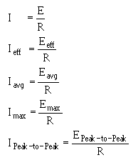
OHM'S LAW IN AC CIRCUITS
� ;�������� ��� �������� ����� ��������� ���-����� �������������� ��� ������������� ���� ����������� �����
���� ��� ����0�� �����$� � ��$��������� ���� � ����������5� � ��������� �� ���� � ������6����������� ��� ��
����� ����� ����� ������$�:� C��.��$�J �������C��.��$������������ ������ ����������� ������� ����$��������$�
���������� �������� ��� ��� ������ ������������� ��� ���-���:� C��.������ � ������������� ��� ���������
����������
� 0� � ���$��� ���������� ���������$�� ������ ������������������� ��������� ������������� ����� �����
-������ � ������:� C��.�������� ����������������
� -��� ���������� ������'���� �� ��� ���<��1��� 5������ �����6���������� ������������� ����� ���$�
� ��� ������������ ��������� � �� ������������� ����� ������ �� �$������������ ����������������� ���$�
� ��� ������������ ����������������� �����-� ���� ������� ������ �������������������'������� �� ���
���� � ��)���� ���� ��� ������ �������������� ������*0��K�!��� ������0��K��!��� �+��������� ������ ���
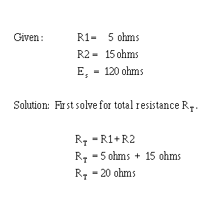
�� �����������������7��� ����6���� ��2���I�
� -���� ������ ����� ����� ������ ������������������ ����� ���*� ���� �� ���������� � ��������������� ��+��
)�� ������:� C��.������ � ���
�
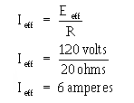
�����
� -������� � $��������$���'��������������������� ��������������*2����+��-�������������������� ����� ���
���������������������������� �������������$����� ����� ��������� ����������'���� �5 � ��� �������������$�
2 �5��
� 4������������ ���2�����L��������� �����(� ( �� ������ ������2������� � �������� �������2�����
� 0� � ���$�����������������:� C��.������ � �������� ����������� ����� �� ������� ��� ������ � ��
����������� � ��� �������� �� ���������������� ������� ��������� ��� ������ � ��
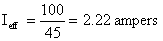
Q41. A series circuit consists of three resistors (R1 = 10Ω, R2 = 20Ω, R3 = 15Ω) and an alternating voltage source of 100 volts. What is the effective value of current in the circuit?
Q42. If the alternating source in Q41 is changed to 200 volts peak-to-peak, what is Iavg?
Q43. If Eeff is 130 volts and Ieff is 3 amperes, what is the total resistance (RT) in the circuit?
�
SUMMARY
� 8�������� ������������������$������������ �� ����� ����������� ���� � � �������������-� ���� ����
� ��� ���������������������� ������ ��������
DC AND ACM< �������������� ���� ������� ���� ����� �$��� ��� ������ ����������� ���������� �� ����� ��� ��� � ���������� ���� ����
ADVANTAGES AND DISADVANTAGES OF AC AND DCM< ����������������������� � � �������������� ���������� ������ ������������< ������������$������5� � �$� ������������������������
�� ����� ��� ���#� ����������� �����) ������ ����������$��������$������������������������ ��� ��� �����
�
��� �
������������������������� �������*����������������������������� ��+��������������� ����� ��� � ����#� ����
������� ������ ���������� ������������ � ������������ �������� ����� ���������� ����������� ��� �$�����
2�0������� �������� ��������� � � �������������� ��� ���������� ������������� ������������� ����������
� ����� ����� ��� ������� ����������� ��� $�����2 � 0������� ���� �������������� � �� ���� �������������� ������
�������� ��
VOLTAGE WAVEFORMSM-���������� ������ ���������������� ��������� �� �� ����������������� ���� ������������������ �������������� ������� ���
ELECTROMAGNETISMM6�������� ����� ��� ����� ������� � � ��������������������� ��� ���������$��������� ��� ���� ��� ������ ������� ���������������������-����������� ����������� �����
�� ����������� ���� ���������� ����� ��� � ���������������������������8��'��� �������� ���� �������������$�
���������������� ����������� ������������������������� �������� ���� ���������� ����� �� ��������������
�
�
���!�
� )���������������� ������� ��� ���� �� �� ���� ����� �� ���������� ���� �������������� ����� ����)�������
*A+��������������������������� ��� �� ��������� ��� �� ������������������� ��� �� ����������� ����$��� ����
����*N+� �� ������������������� ��� �� ���������������
� 6����������>���������� � �������������������������� �������� ��� ���� ��$����� ����� ��� � ���
����������������������� ��������������6����������������� ���������������������� ��� ������� ���
� ���� ���$������ � ��������������������������������������������
�
MAGNETIC FIELD OF A COILM6����� ��� ���������������������$� ����� ����&:2.��-��� ����� ��� � �������������������������� ���� �������� ��� � ����-����� � ���� �� ���������� ��������
� � ������������������������������������ ��� � ��� ����������������� � ������ �������
� 6��������� ���� �������������� �������� � ����������$������� �� ���������������� ��� � ����������� � ��
����������
� -������������������� ����� ��� � ����������� � ������������������
• -����� ��������������������� ��� �������� ��
• -���� ���������������� �������� ��
• -������ ����������� � ��������������� �� �����
�
���"�
• -����������� ���� � � ������������
BASIC AC GENERATIONM6���������������� �� ���� ����� ��� � ������� ���������� � ��������� ���������� ����$����� ��*�� ����+� �� ������� �����������������-� ��������� ���� ���� ����� ����� ��
����� ����
� )� �������� �������� ��� ���� ����� ��� � ��������������� ������� ����������� ���������� ��� � �����
����� ���� ����-���������� ���������� ���� ������ ������������ ��������� �� �� ���������� ������ ���
��������*��+��:����� � �������� �� ���*�"7E +���������������������������������� ���������-������ �� ��
�� �������������� ������ ���������� � ���� ������ �������������� ���� ������ ����:������ �������� ������
������� ���#�� ����������@�*��,@+��
FREQUENCYM-����� ���������� �������������������� ���������������������90/H�/1&4��)&� ���#������ �� �������� ������@��;��������#� � ���� ��������������#����������� ��������� ���������
���������
PERIODM-���� ����#� ��������� � ����������� �������������� � ���� �������G/02:<�:9�-,/� 6)=/��
� /�������� �������� ���� �������������� ������ �����-���� ������ ����� ������������� �������� ������
� �������� ����� � ��� ���� ���������� � ���� ������ ����-���� ������ ����� ������������� �������� ������
� �������� ������� ��� ���� ������������ ���� ������ ����2���������� ������ �������$���������� ������ ����
���� ���� �� � ��� @�����������$���������� ��� ���� �� ����
� -������ ��������� �������� �� ������ ��������� ��� �����������#�����D�����$������ ������������#�����$�
������������������� ����-��� ���� �� �� ��� �� ���� ������������ ���������#����������
�
���%�
WAVELENGTHM-������ ��������� �������� ����� ������������ �� ����'�������� � ����������� ��� -���� ������������������ ����������� ����� ����� ��� ������������������������� �������6��� ������ ��
�� ��������� � ����*�+����� �� ����������� ����� ��������� ����������� �*� �������+��������
���������� ����� ������������5��������� ��
PEAK AND PEAK-TO-PEAK VALUESM-��� �5 � ��� �������������� �������� ������ ������ ��� �������� ���������'��� ����-��� �5 � ������������ ���������� � ���� ������ ���������� �5 � �
�� �������������� ������������ ���� ������ ��� ���������'�������'��� ����-������'�������'��� ��� ���� ���
�������'��� ����
�
���(�
INSTANTANEOUS VALUEM-��� ��������������� ��������� ������������ ������ ����� �������� �������� �������� �������� ��������������������������� �� ��� ����������� ���-������������ �� � ����� �������
��������������� ������������@���������������'��� ����
AVERAGE VALUEM-������������� ��������� ������������� ���������������� ������������������ � ���� ��������������� ������� �������� ������ ����-������������� ��� ���#�� ����7�"�"�����������'��� ����
-������ � ����������������� ������������������������������
0� � �����-������������� ���*/�������2����+� ����������� ������ ����� ���-������������� ���������� � ����
� �������� ��@�����
EFFECTIVE VALUEM-��������� ����� ���������� ������ ���������������� ����� �������� ������ � ������ ���������������� ������������������������� ��� ������������� ������� �� ����� ��������������� ��
������������ �������� ���� ������������� ������������������ �������������� ���� ����-��������� ����� ���
������ �������� ���#�� ����7�%7%�� ����������'��� ����-��������� ����� ��� ��� ����� ������������ ����
�#��������� ���� ����
� -������ �� ���� ��� ��������������� ����������������������� � ������������� ����� ��������� ��������
����� ������� ��������������� �������� �����������������4�������� �������� ���� ��������������������� �����
�����' ����#�� ��������� ��������������� ������������ �������������5����� ��������#�����������������
����������������� �������� ��������������� �����-� �� ��������������� ��0����;�����#������*� �+��� ���
�� ������ ��
� -������ � ������������� ������� �5 � ��� ��������� ����������������������
�
���?�
SINE WAVES IN PHASEM6��������� ��������������5��� �� �������� �������������$������������ �� ������ ���������-����� �������$������� ��������� ������������������ �� � � ����� �5 � ��� �������
������ ��� ������ �������� ��� ���� ����
SINE WAVES OUT OF PHASEM6��������� ����������������������� �� � � ����� �5 � � �� �������� ��������� ��$���������� ����������5 ��������������� ��-������������������� ���������������
������� ���������������-������� ����� ��������� ��������$�������� �� �������� �������������-�������������
�������� ��� � � �*��� �5 � +��� ���� ���� ���� ����� ��������������������-������ � ��� ����������
����� ������������������������� ��� � � �*��� �5 � +��� ����� ��� ������������� ���������������
6������� �������� ������� ������� ��� ������ ��� ��$������ ��������� ���������� ������ ����������9���
�5� � �$������/�� ����������/������?7E $���������/�� ���������/������?7E ��0� � �����-���� ���������
����� �������������� ����������������5�����7E ������"7E ��-���� ��������������� ��������7E ��������"7E �����
���� ������������ ���������-���� ����������������������� ��� ���� �� ������������� ���������(7E ������� �����
���������������$�������������������������������� �� � � ����� �5 � ��� ������������� ��� ���
�
���7�
OHM'S LAW IN AC CIRCUITM) ������ ������� ������� ������������ ��� ������������ ����� �� ��� ��������-��� ���������� �������� � ���� ���<������ 5������ �����:� C��.������ � ����������� ��� ���
����� ������ ����
�
�
�����
ANSWERS TO QUESTIONS Q1. THROUGH Q43.
A1. An electrical current which flows in one direction only.
A2. An electrical current which is constantly varying in amplitude, and which changes direction at regular intervals.
A3. The dc voltage must be generated at the level required by the load.
A4. The I 2R power loss is excessive.
A5. Alternating current (ac).
A6. The needle aligns itself at right angles to the conductor.
A7. (a) clockwise (b) counterclockwise.
A8. It is used to determine the relation between the direction of the magnetic lines of force around a conductor and the direction of current through the conductor.
A9. The north pole of the compass will point in the direction of the magnetic lines of force.
A10. It combines with the other field.
A11. It deforms the other field.
A12. (a) The field consists of concentric circles in a plane perpendicular to the wire (b) the field of each turn of wire links with the fields of adjacent turns producing a two-pole field similar in shape to that of a simple bar magnet.
A13. The polarity of the two-pole field reverses.
A14. Use the left-hand rule for coils.
A15. Grasp the coil in your left hand, with your fingers "wrapped around" in the direction of electron flow. The thumb will point toward the north pole.
A16. (a) When the conductors are cutting directly across the magnetic lines of force (at the 90º and 270º points). (b) When the conductors are moving parallel to the magnetic lines of force (at the 0° , 180° , and 360° points).
A17. 360° .
A18. Extend your left hand so that your thumb points in the direction of conductor movement, and your forefinger points in the direction of the magnetic flux (north to south). Now point your middle finger 90° from the forefinger and it will point in the direction of electron current flow in the conductor.
A19. Continuous rotation of the conductor through magnetic fines of force produces a series of cycles of alternating voltage or, in other words, an alternating voltage or a sine wave of voltage.
A20. Frequency is the number of complete cycles of alternating voltage or current completed each second.
�
�����
A21. Period.
A22. A positive alternation is the positive variation in the voltage or current of a sine curve.
A23. The period measures time and the wavelength measures distance.
A24. The peak value is the maximum value of one alternation; the peak-to-peak value is twice the maximum or peak value.
A25. Twice.
A26. The instantaneous value (Einst or Iinst)
A27. Average value (Eavg or Iavg)
A28. Zero
A29.
A30.
A31.
A32. The power (heat) produced in a resistance by a dc voltage is compared to that produced in the same resistance by an ac voltage of the same peak amplitude.
A33. The effective value.
A34.
�
�����
A35.
A36.
(Remember: Unless specified otherwise, the voltage or current value is always considered to be the effective value.)
A37. When the two waves go through their maximum and minimum points at the same time and in the same direction.
A38. When the waves do not go through their maximum and minimum points at the same time, a PHASE DIFFERENCE exists, and the two waves are said to be out of phase. (Two waves are also considered to be out of phase if they differ in phase by 180° and their instantaneous voltages are always of opposite polarity, even though both waves go through their maximum and minimum points at the same time).
A39. They are in phase with each other.
A40. Locate the points on the time axis where the two waves cross traveling in the same direction. The number of degrees between these two points is the phase difference.
A41.
A42. Iavg = 0.636 × Imax = 1.41 amperes.
A43. 43.3 ohms.
2-1
CHAPTER 2
INDUCTANCE
LEARNING OBJECTIVES
Upon completion of this chapter you will be able to:
1. Write the basic unit of and the symbol for inductance.
2. State the type of moving field used to generate an emf in a conductor.
3. Define the term "inductance."
4. State the meanings of the terms "induced emf" and "counter emf."
5. State Lenz's law.
6. State the effect that inductance has on steady direct current, and direct current that is changing in magnitude.
7. List five factors that affect the inductance of a coil, and state how various physical changes in these factors affect inductance.
8. State the principles and sequences involved in the buildup and decay of current in an LR series circuit.
9. Write the formula for computing one time constant in an LR series circuit.
10. Solve L/R time constant problems.
11. State the three types of power loss in an inductor.
12. Define the term "mutual inductance."
13. State the meaning of the term "coupled circuits."
14. State the meaning of the term "coefficient of coupling."
15. Given the inductance values of and the coefficient of coupling between two series-connected inductors, solve for mutual inductance, M.
16. Write the formula for the "total inductance" of two inductors connected in series-opposing.
17. Given the inductance values of and the mutual inductance value between two coils connected in series-aiding, solve for their combined inductance, LT.
2-2
INDUCTANCE
The study of inductance presents a very challenging but rewarding segment of electricity. It is challenging in the sense that, at first, it will seem that new concepts are being introduced. You will realize as this chapter progresses that these "new concepts" are merely extensions and enlargements of fundamental principles that you learned previously in the study of magnetism and electron physics. The study of inductance is rewarding in the sense that a thorough understanding of it will enable you to acquire a working knowledge of electrical circuits more rapidly.
CHARACTERISTICS OF INDUCTANCE
Inductance is the characteristic of an electrical circuit that opposes the starting, stopping, or a change in value of current. The above statement is of such importance to the study of inductance that it bears repeating. Inductance is the characteristic of an electrical conductor that OPPOSES CHANGE in CURRENT. The symbol for inductance is L and the basic unit of inductance is the HENRY (H). One henry is equal to the inductance required to induce one volt in an inductor by a change of current of one ampere per second.
You do not have to look far to find a physical analogy of inductance. Anyone who has ever had to push a heavy load (wheelbarrow, car, etc.) is aware that it takes more work to start the load moving than it does to keep it moving. Once the load is moving, it is easier to keep the load moving than to stop it again. This is because the load possesses the property of INERTIA. Inertia is the characteristic of mass which opposes a CHANGE in velocity. Inductance has the same effect on current in an electrical circuit as inertia has on the movement of a mechanical object. It requires more energy to start or stop current than it does to keep it flowing.
Q1. What is the basic unit of inductance and the abbreviation for this unit?
ELECTROMOTIVE FORCE (EMF)
You have learned that an electromotive force is developed whenever there is relative motion between a magnetic field and a conductor.
Electromotive force is a difference of potential or voltage which exists between two points in an electrical circuit. In generators and inductors the emf is developed by the action between the magnetic field and the electrons in a conductor. This is shown in figure 2-1.
Figure 2-1.—Generation of an emf in an electrical conductor.
2-3
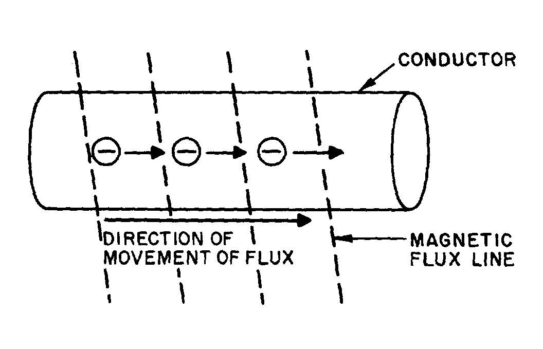
When a magnetic field moves through a stationary metallic conductor, electrons are dislodged from their orbits. The electrons move in a direction determined by the movement of the magnetic lines of flux. This is shown below:
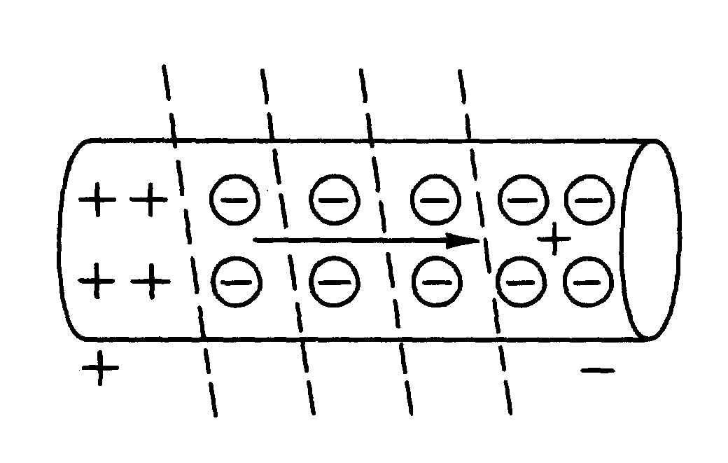
The electrons move from one area of the conductor into another area. The area that the electrons moved from has fewer negative charges (electrons) and becomes positively charged. The area the electrons move into becomes negatively charged. This is shown below:
The difference between the charges in the conductor is equal to a difference of potential (or voltage). This voltage caused by the moving magnetic field is called electromotive force (emf).
In simple terms, the action of a moving magnetic field on a conductor can be compared to the action of a broom. Consider the moving magnetic field to be a moving broom. As the magnetic broom moves along (through) the conductor, it gathers up and pushes electrons before it, as shown below:
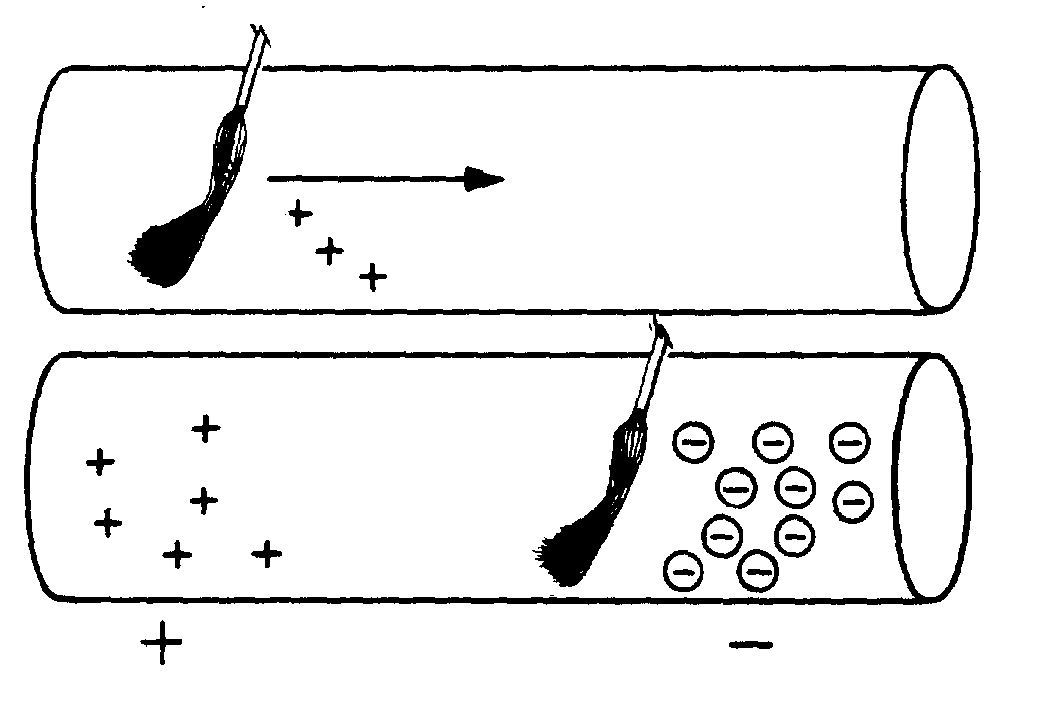
2-4
The area from which electrons are moved becomes positively charged, while the area into which electrons are moved becomes negatively charged. The potential difference between these two areas is the electromotive force or emf.
Q2. An emf is generated in a conductor when the conductor is cut by what type of field?
SELF-INDUCTANCE
Even a perfectly straight length of conductor has some inductance. As you know, current in a conductor produces a magnetic field surrounding the conductor. When the current changes, the magnetic field changes. This causes relative motion between the magnetic field and the conductor, and an electromotive force (emf) is induced in the conductor. This emf is called a SELF-INDUCED EMF because it is induced in the conductor carrying the current. The emf produced by this moving magnetic field is also referred to as COUNTER ELECTROMOTIVE FORCE (cemf). The polarity of the counter electromotive force is in the opposite direction to the applied voltage of the conductor. The overall effect will be to oppose a change in current magnitude. This effect is summarized by Lenz's law which states that: THE INDUCED EMF IN ANY CIRCUIT IS ALWAYS IN A DIRECTION TO OPPOSE THE EFFECT THAT PRODUCED IT.
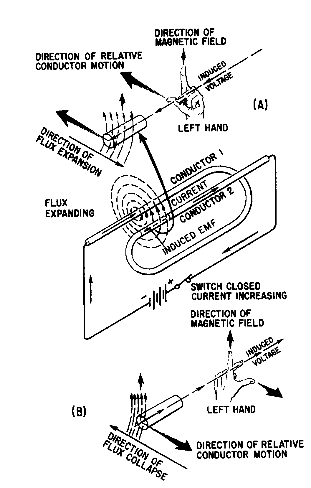
If the shape of the conductor is changed to form a loop, then the electromagnetic field around each portion of the conductor cuts across some other portion of the same conductor. This is shown in its simplest form in figure 2-2. A length of conductor is looped so that two portions of the conductor lie next to each other. These portions are labeled conductor 1 and conductor 2. When the switch is closed, current (electron flow) in the conductor produces a magnetic field around ALL portions of the conductor. For simplicity, the magnetic field (expanding lines of flux) is shown in a single plane that is perpendicular to both conductors. Although the expanding field of flux originates at the same time in both conductors, it is considered as originating in conductor 1 and its effect on conductor 2 will be explained. With increasing current, the flux field expands outward from conductor 1, cutting across a portion of conductor 2. This results in an induced emf in conductor 2 as shown by the dashed arrow. Note that the induced emf is in the opposite direction to (in OPPOSITION to) the battery current and voltage, as stated in Lenz's law.
2-5
Figure 2-2.—Self-inductance.
The direction of this induced voltage may be determined by applying the LEFT-HAND RULE FOR GENERATORS. This rule is applied to a portion of conductor 2 that is "lifted" and enlarged for this purpose in figure 2-2(A). This rule states that if you point the thumb of your left hand in the direction of relative motion of the conductor and your index finger in the direction of the magnetic field, your middle finger, extended as shown, will now indicate the direction of the induced current which will generate the induced voltage (cemf) as shown.
In figure 2-2(B), the same section of conductor 2 is shown after the switch has been opened. The flux field is collapsing. Applying the left-hand rule in this case shows that the reversal of flux MOVEMENT has caused a reversal in the direction of the induced voltage. The induced voltage is now in the same direction as the battery voltage. The most important thing for you to note is that the self-induced voltage opposes BOTH changes in current. That is, when the switch is closed, this voltage delays the initial buildup of current by opposing the battery voltage. When the switch is opened, it keeps the current flowing in the same direction by aiding the battery voltage.
Thus, from the above explanation, you can see that when a current is building up it produces an expanding magnetic field. This field induces an emf in the direction opposite to the actual flow of current.
2-6
This induced emf opposes the growth of the current and the growth of the magnetic field. If the increasing current had not set up a magnetic field, there would have been no opposition to its growth. The whole reaction, or opposition, is caused by the creation or collapse of the magnetic field, the lines of which as they expand or contract cut across the conductor and develop the counter emf.
Since all circuits have conductors in them, you can assume that all circuits have inductance. However, inductance has its greatest effect only when there is a change in current. Inductance does NOT oppose current, only a CHANGE in current. Where current is constantly changing as in an ac circuit, inductance has more effect.
Q3. Define inductance.
Q4. What is meant by induced emf? By counter emf?
Q5. State Lenz's law.
Q6. What effect does inductance have (a) on steady direct current and (b) on direct current while it is changing in amplitude?
To increase the property of inductance, the conductor can be formed into a loop or coil. A coil is also called an inductor. Figure 2-3 shows a conductor formed into a coil. Current through one loop produces a magnetic field that encircles the loop in the direction as shown in figure 2-3(A). As current increases, the magnetic field expands and cuts all the loops as shown in figure 2-3(B). The current in each loop affects all other loops. The field cutting the other loop has the effect of increasing the opposition to a current change.
(A) (B) Figure 2-3.—Inductance.
Inductors are classified according to core type. The core is the center of the inductor just as the core of an apple is the center of an apple. The inductor is made by forming a coil of wire around a core. The core material is normally one of two basic types: soft-iron or air. An iron-core inductor and its schematic symbol (which is represented with lines across the top of it to indicate the presence of an iron core) are shown, in figure 2-4(A). The air-core inductor may be nothing more than a coil of wire, but it is usually a coil formed around a hollow form of some nonmagnetic material such as cardboard. This material serves no purpose other than to hold the shape of the coil. An air-core inductor and its schematic symbol are shown in figure 2-4(B).
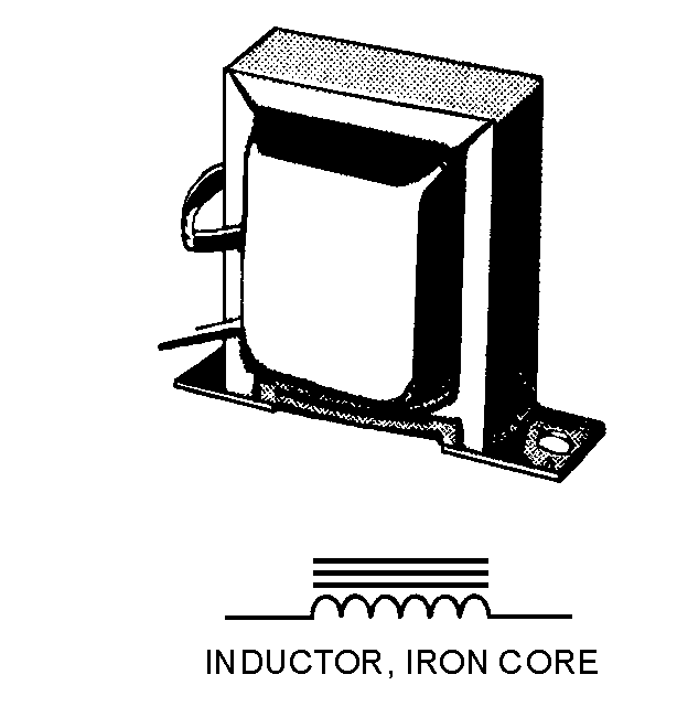
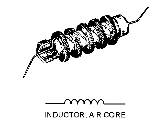
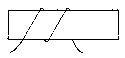
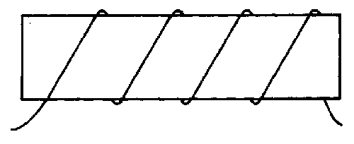
2-7
(A) (B) Figure 2-4.—Inductor types and schematic symbols.
Factors Affecting Coil Inductance
There are several physical factors which affect the inductance of a coil. They include the number of turns in the coil, the diameter of the coil, the coil length, the type of material used in the core, and the number of layers of winding in the coils.
Inductance depends entirely upon the physical construction of the circuit, and can only be measured with special laboratory instruments. Of the factors mentioned, consider first how the number of turns affects the inductance of a coil. Figure 2-5 shows two coils. Coil (A) has two turns and coil (B) has four turns. In coil (A), the flux field set up by one loop cuts one other loop. In coil (B), the flux field set up by one loop cuts three other loops. Doubling the number of turns in the coil will produce a field twice as strong, if the same current is used. A field twice as strong, cutting twice the number of turns, will induce four times the voltage. Therefore, it can be said that the inductance varies as the square of the number of turns.
(A) (B) Figure 2-5.—Inductance factor (turns).
The second factor is the coil diameter. In figure 2-6 you can see that the coil in view B has twice the diameter of coil view A. Physically, it requires more wire to construct a coil of large diameter than one of small diameter with an equal number of turns. Therefore, more lines of force exist to induce a counter emf
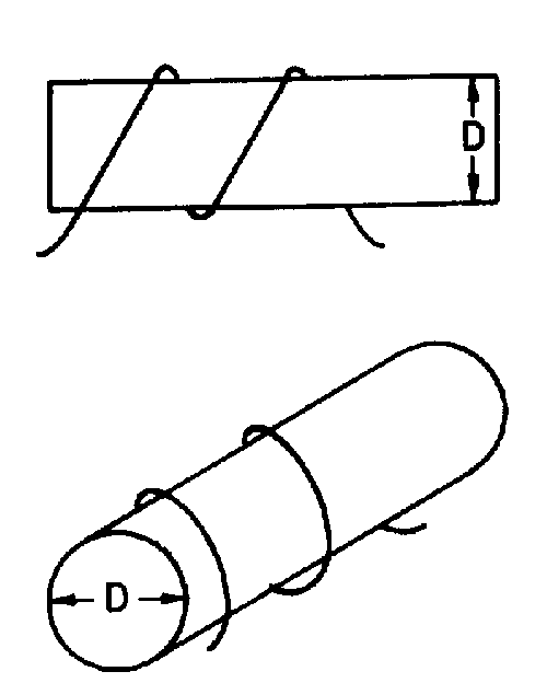
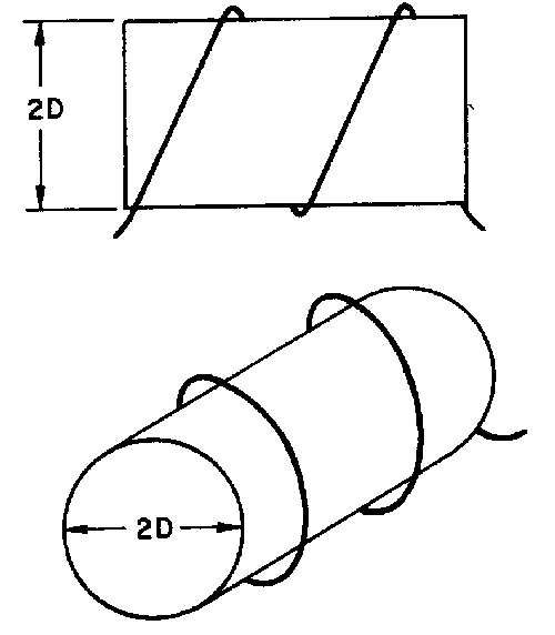
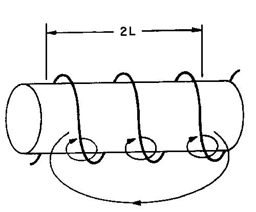
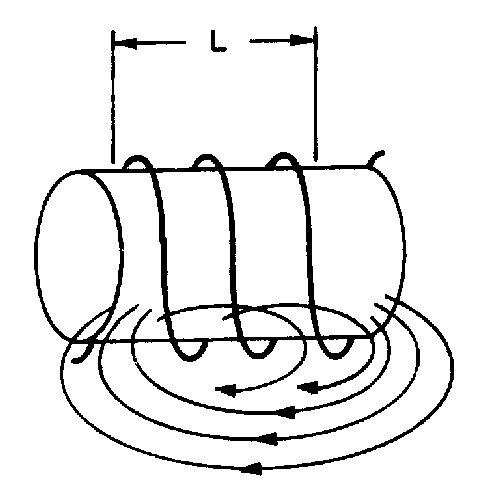
2-8
in the coil with the larger diameter. Actually, the inductance of a coil increases directly as the cross- sectional area of the core increases. Recall the formula for the area of a circle: A = πr2. Doubling the radius of a coil increases the inductance by a factor of four.
(A) (B) Figure 2-6.—Inductance factor (diameter).
The third factor that affects the inductance of a coil is the length of the coil. Figure 2-7 shows two examples of coil spacings. Coil (A) has three turns, rather widely spaced, making a relatively long coil. A coil of this type has few flux linkages, due to the greater distance between each turn. Therefore, coil (A) has a relatively low inductance. Coil (B) has closely spaced turns, making a relatively short coil. This close spacing increases the flux linkage, increasing the inductance of the coil. Doubling the length of a coil while keeping the same number of turns halves the value of inductance.
(A) (B)
Figure 2-7.—Inductance factor (coil length). CLOSELY WOUND
The fourth physical factor is the type of core material used with the coil. Figure 2-8 shows two coils: Coil (A) with an air core, and coil (B) with a soft-iron core. The magnetic core of coil (B) is a better path for magnetic lines of force than is the nonmagnetic core of coil (A). The soft-iron magnetic core's high
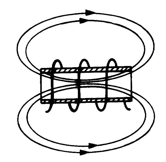
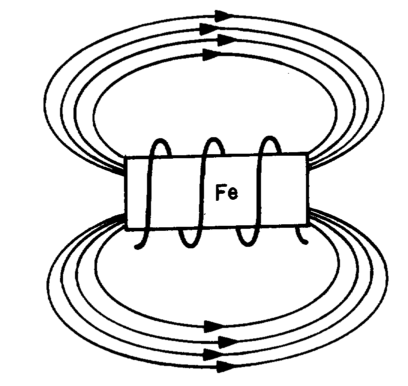
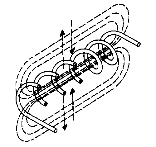
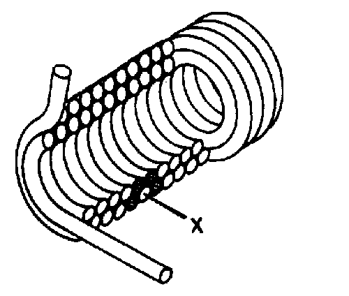
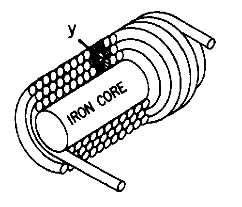
2-9
permeability has less reluctance to the magnetic flux, resulting in more magnetic lines of force. This increase in the magnetic lines of force increases the number of lines of force cutting each loop of the coil, thus increasing the inductance of the coil. It should now be apparent that the inductance of a coil increases directly as the permeability of the core material increases.
(A) AIR CORE (B) SOFT-IRON CORE Figure 2-8.—Inductance factor (core material).
Another way of increasing the inductance is to wind the coil in layers. Figure 2-9 shows three cores with different amounts of layering. The coil in figure 2-9(A) is a poor inductor compared to the others in the figure because its turns are widely spaced and there is no layering. The flux movement, indicated by the dashed arrows, does not link effectively because there is only one layer of turns. A more inductive coil is shown in figure 2-9(B). The turns are closely spaced and the wire has been wound in two layers. The two layers link each other with a greater number of flux loops during all flux movements. Note that nearly all the turns, such as X, are next to four other turns (shaded). This causes the flux linkage to be increased.
(A)
(B) (C) Figure 2-9.—Coils of various inductances.

2-10
A coil can be made still more inductive by winding it in three layers, as shown in figure 2-9(C). The increased number of layers (cross-sectional area) improves flux linkage even more. Note that some turns, such as Y, lie directly next to six other turns (shaded). In actual practice, layering can continue on through many more layers. The important fact to remember, however, is that the inductance of the coil increases with each layer added.
As you have seen, several factors can affect the inductance of a coil, and all of these factors are variable. Many differently constructed coils can have the same inductance. The important information to remember, however, is that inductance is dependent upon the degree of linkage between the wire conductor(s) and the electromagnetic field. In a straight length of conductor, there is very little flux linkage between one part of the conductor and another. Therefore, its inductance is extremely small. It was shown that conductors become much more inductive when they are wound into coils. This is true because there is maximum flux linkage between the conductor turns, which lie side by side in the coil.
Q7.
a. List five factors that affect the inductance of a coil.
b. Bending a straight piece of wire into a loop or coil has what effect on the inductance of the wire?
c. Doubling the number of turns in a coil has what effect on the inductance of the coil?
d. Decreasing the diameter of a coil has what effect on the inductance of the coil?
e. Inserting a soft-iron core into a coil has what effect on the inductance of the coil?
f. Increasing the number of layers of windings in a coil has what effect on the inductance of the coil?
UNIT OF INDUCTANCE
As stated before, the basic unit of inductance (L) is the HENRY (H), named after Joseph Henry, the co-discoverer with Faraday of the principle of electromagnetic induction. An inductor has an inductance of 1 henry if an emf of 1 volt is induced in the inductor when the current through the inductor is changing at the rate of 1 ampere per second. The relationship between the induced voltage, the inductance, and the rate of change of current with respect to time is stated mathematically as:
where Eind is the induced emf in volts; L is the inductance in henrys; and ∆I is the change in current in amperes occurring in ∆t seconds. The symbol ∆ (Greek letter delta), means "a change in ....". The henry is a large unit of inductance and is used with relatively large inductors. With small inductors, the millihenry is used. (A millihenry is equal to 1 × 10⁻³ henry, and one henry is equal to 1,000 millihenrys.) For still smaller inductors the unit of inductance is the microhenry (µH). (A µH = 1 × 10 -6H, and one henry is equal to 1,000,000 microhenrys.)
GROWTH AND DECAY OF CURRENT IN AN LR SERIES CIRCUIT
When a battery is connected across a "pure" inductance, the current builds up to its final value at a rate determined by the battery voltage and the internal resistance of the battery. The current buildup is
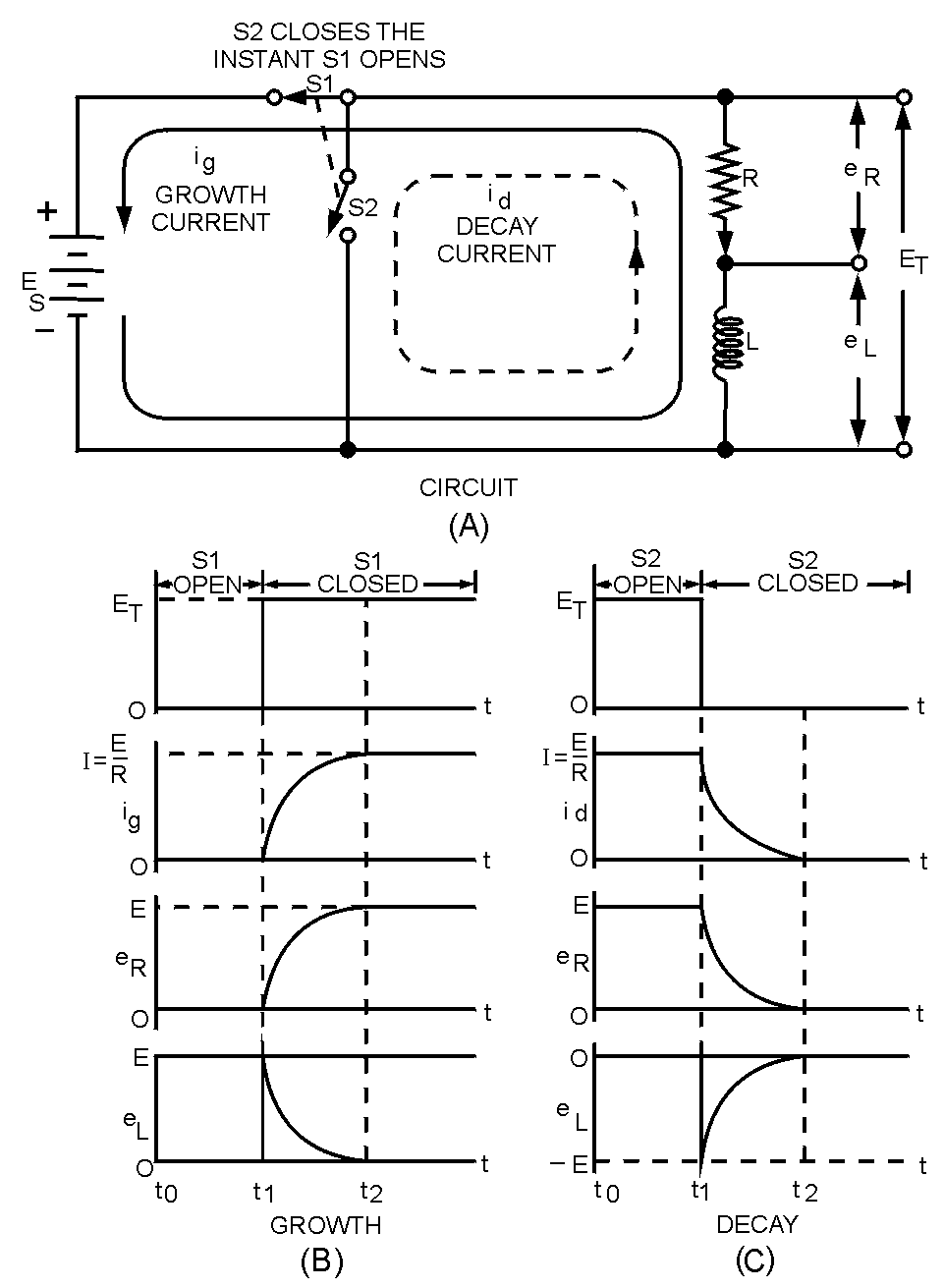
2-11
gradual because of the counter emf generated by the self-inductance of the coil. When the current starts to flow, the magnetic lines of force move outward from the coil. These lines cut the turns of wire on the inductor and build up a counter emf that opposes the emf of the battery. This opposition causes a delay in the time it takes the current to build up to a steady value. When the battery is disconnected, the lines of force collapse. Again these lines cut the turns of the inductor and build up an emf that tends to prolong the flow of current.
A voltage divider containing resistance and inductance may be connected in a circuit by means of a special switch, as shown in figure 2-10(A). Such a series arrangement is called an LR series circuit.
Figure 2-10.—Growth and decay of current in an LR series circuit.
When switch S1 is closed (as shown), a voltage ES appears across the voltage divider. At this instant the current will attempt to increase to its maximum value. However, this instantaneous current change causes coil L to produce a back EMF, which is opposite in polarity and almost equal to the EMF of the source. This back EMF opposes the rapid current change. Figure 2-10(B) shows that at the instant switch S1 is closed, there is no measurable growth current (ig), a minimum voltage drop is across resistor R, and maximum voltage exists across inductor L.
As current starts to flow, a voltage (eR) appears across R, and the voltage across the inductor is reduced by the same amount. The fact that the voltage across the inductor (L) is reduced means that the
2-12
growth current (ig) is increased and consequently eR is increased. Figure 2-10(B) shows that the voltage across the inductor (eL) finally becomes zero when the growth current (ig) stops increasing, while the voltage across the resistor (eR) builds up to a value equal to the source voltage (ES).
Electrical inductance is like mechanical inertia, and the growth of current in an inductive circuit can be likened to the acceleration of a boat on the surface of the water. The boat does not move at the instant a constant force is applied to it. At this instant all the applied force is used to overcome the inertia of the boat. Once the inertia is overcome the boat will start to move. After a while, the speed of the boat reaches its maximum value and the applied force is used up in overcoming the friction of the water against the hull.
When the battery switch (S1) in the LR circuit of figure 2-10(A) is closed, the rate of the current increase is maximum in the inductive circuit. At this instant all the battery voltage is used in overcoming the emf of self-induction which is a maximum because the rate of change of current is maximum. Thus the battery voltage is equal to the drop across the inductor and the voltage across the resistor is zero. As time goes on more of the battery voltage appears across the resistor and less across the inductor. The rate of change of current is less and the induced emf is less. As the steady-state condition of the current is approached, the drop across the inductor approaches zero and all of the battery voltage is "dropped" across the resistance of the circuit.
Thus the voltages across the inductor and the resistor change in magnitude during the period of growth of current the same way the force applied to the boat divides itself between the effects of inertia and friction. In both examples, the force is developed first across the inertia/inductive effect and finally across the friction/resistive effect.
Figure 2-10(C) shows that when switch S2 is closed (source voltage ES removed from the circuit), the flux that has been established around the inductor (L) collapses through the windings. This induces a voltage eL in the inductor that has a polarity opposite to ES and is essentially equal to ES in magnitude. The induced voltage causes decay current (id) to flow in resistor R in the same direction in which current was flowing originally (when S1 was closed). A voltage (eR) that is initially equal to source voltage (ES) is developed across R. The voltage across the resistor (eR) rapidly falls to zero as the voltage across the inductor (eL) falls to zero due to the collapsing flux.
Just as the example of the boat was used to explain the growth of current in a circuit, it can also be used to explain the decay of current in a circuit. When the force applied to the boat is removed, the boat still continues to move through the water for a while, eventually coming to a stop. This is because energy was being stored in the inertia of the moving boat. After a period of time the friction of the water overcomes the inertia of the boat, and the boat stops moving. Just as inertia of the boat stored energy, the magnetic field of an inductor stores energy. Because of this, even when the power source is removed, the stored energy of the magnetic field of the inductor tends to keep current flowing in the circuit until the magnetic field collapse.
Q8.
a. When voltage is first applied to a series LR circuit, how much opposition does the inductance have to the flow of current compared to that of the circuit resistance?
b. In a series circuit containing a resistor (R 1) and an inductor (L1), what voltage exists across R1 when the counter emf is at its maximum value?
c. What happens to the voltage across the resistance in an LR circuit during current buildup in the circuit, and during current decay in the circuit?
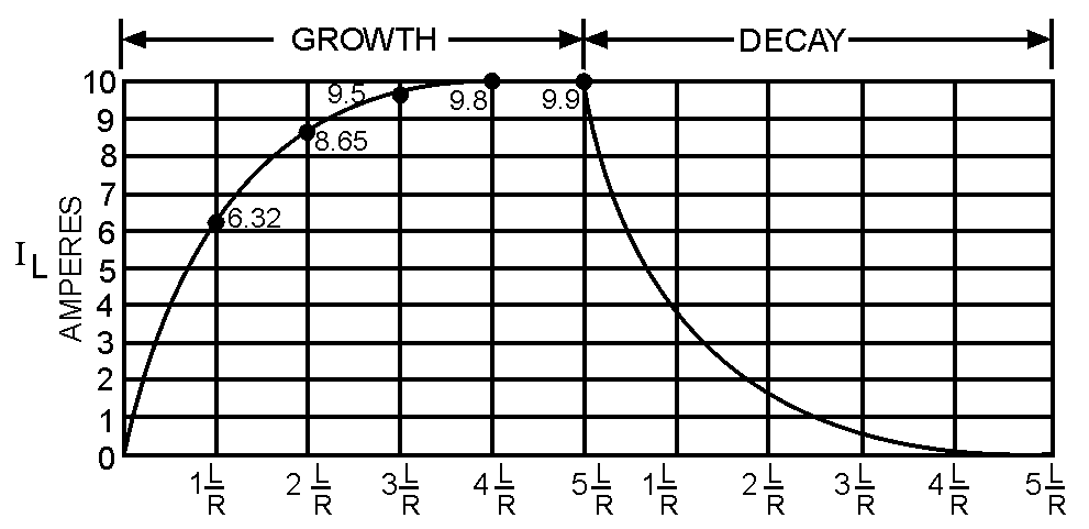
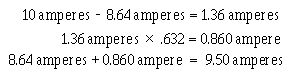
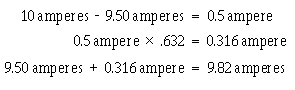
2-13
L/R Time Constant
The L/R TIME CONSTANT is a valuable tool for use in determining the time required for current in an inductor to reach a specific value. As shown in figure 2-11, one L/R time constant is the time required for the current in an inductor to increase to 63 percent (actually 63.2 percent) of the maximum current. Each time constant is equal to the time required for the current to increase by 63.2 percent of the difference in value between the current flowing in the inductor and the maximum current. Maximum current flows in the inductor after five L/R time constants are completed. The following example should clear up any confusion about time constants. Assume that maximum current in an LR circuit is 10 amperes. As you know, when the circuit is energized, it takes time for the current to go from zero to 10 amperes. When the first time constant is completed, the current in the circuit is equal to 63.2% of 10 amperes. Thus the amplitude of current at the end of 1 time constant is 6.32 amperes.
Figure 2-11.—L/R time constant.
During the second time constant, current again increases by 63.2% (.632) of the difference in value between the current flowing in the inductor and the maximum current. This difference is 10 amperes minus 6.32 amperes and equals 3.68 amperes; 63.2% of 3.68 amperes is 2.32 amperes. This increase in current during the second time constant is added to that of the first time constant. Thus, upon completion of the second time constant, the amount of current in the LR circuit is 6.32 amperes + 2.32 amperes = 8.64 amperes.
During the third constant, current again increases:
During the fourth time constant, current again increases:
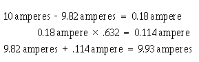
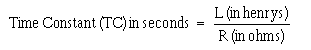
2-14
During the fifth time constant, current increases as before:
Thus, the current at the end of the fifth time constant is almost equal to 10.0 amperes, the maximum current. For all practical purposes the slight difference in value can be ignored.
When an LR circuit is deenergized, the circuit current decreases (decays) to zero in five time constants at the same rate that it previously increased. If the growth and decay of current in an LR circuit are plotted on a graph, the curve appears as shown in figure 2-11. Notice that current increases and decays at the same rate in five time constants.
The value of the time constant in seconds is equal to the inductance in henrys divided by the circuit resistance in ohms.
The formula used to calculate one L/R time constant is:
Q9. What is the formula for one L/R time constant?
Q10.
a. The maximum current applied to an inductor is 1.8 amperes. How much current flowed in the inductor 3 time constants after the circuit was first energized?
b. What is the minimum number of time constants required for the current in an LR circuit to increase to its maximum value?
c. A circuit containing only an inductor and a resistor has a maximum of 12 amperes of applied current flowing in it. After 5 L/R time constants the circuit is opened. How many time constants is required for the current to decay to 1.625 amperes?
POWER LOSS IN AN INDUCTOR
Since an inductor (coil) consists of a number of turns of wire, and since all wire has some resistance, every inductor has a certain amount of resistance. Normally this resistance is small. It is usually neglected in solving various types of ac circuit problems because the reactance of the inductor (the opposition to alternating current, which will be discussed later) is so much greater than the resistance that the resistance has a negligible effect on the current.
However, since some inductors are designed to carry relatively large amounts of current, considerable power can be dissipated in the inductor even though the amount of resistance in the inductor is small. This power is wasted power and is called COPPER LOSS. The copper loss of an inductor can be calculated by multiplying the square of the current in the inductor by the resistance of the winding (I2R).
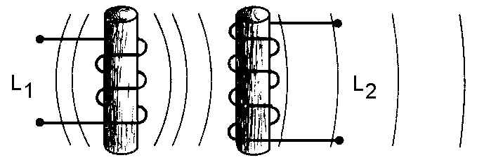
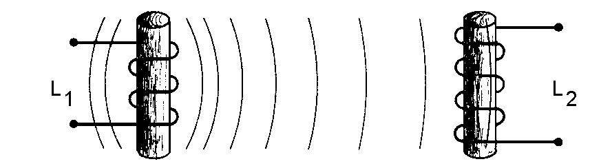
2-15
In addition to copper loss, an iron-core coil (inductor) has two iron losses. These are called HYSTERESIS LOSS and EDDY-CURRENT LOSS. Hysteresis loss is due to power that is consumed in reversing the magnetic field of the inductor core each time the direction of current in the inductor changes.
Eddy-current loss is due to heating of the core by circulating currents that are induced in the iron core by the magnetic field around the turns of the coil. These currents are called eddy currents and circulate within the iron core only.
All these losses dissipate power in the form of heat. Since this power cannot be returned to the electrical circuit, it is lost power.
Q11. State three types of power loss in an inductor.
MUTUAL INDUCTANCE
Whenever two coils are located so that the flux from one coil links with the turns of the other coil, a change of flux in one coil causes an emf to be induced in the other coil. This allows the energy from one coil to be transferred or coupled to the other coil. The two coils are said to be coupled or linked by the property of MUTUAL INDUCTANCE (M). The amount of mutual inductance depends on the relative positions of the two coils. This is shown in figure 2-12. If the coils are separated a considerable distance, the amount of flux common to both coils is small and the mutual inductance is low. Conversely, if the coils are close together so that nearly all the flux of one coil links the turns of the other, the mutual inductance is high. The mutual inductance can be increased greatly by mounting the coils on a common iron core.
(A) INDUCTORS CLOSE – LARGE M
(B) INDUCTORS FAR APART - SMALL M
( C) INDUCTOR AXES PERPENDICULAR – NO M Figure 2-12.—The effect of position of coils on mutual inductance (M).
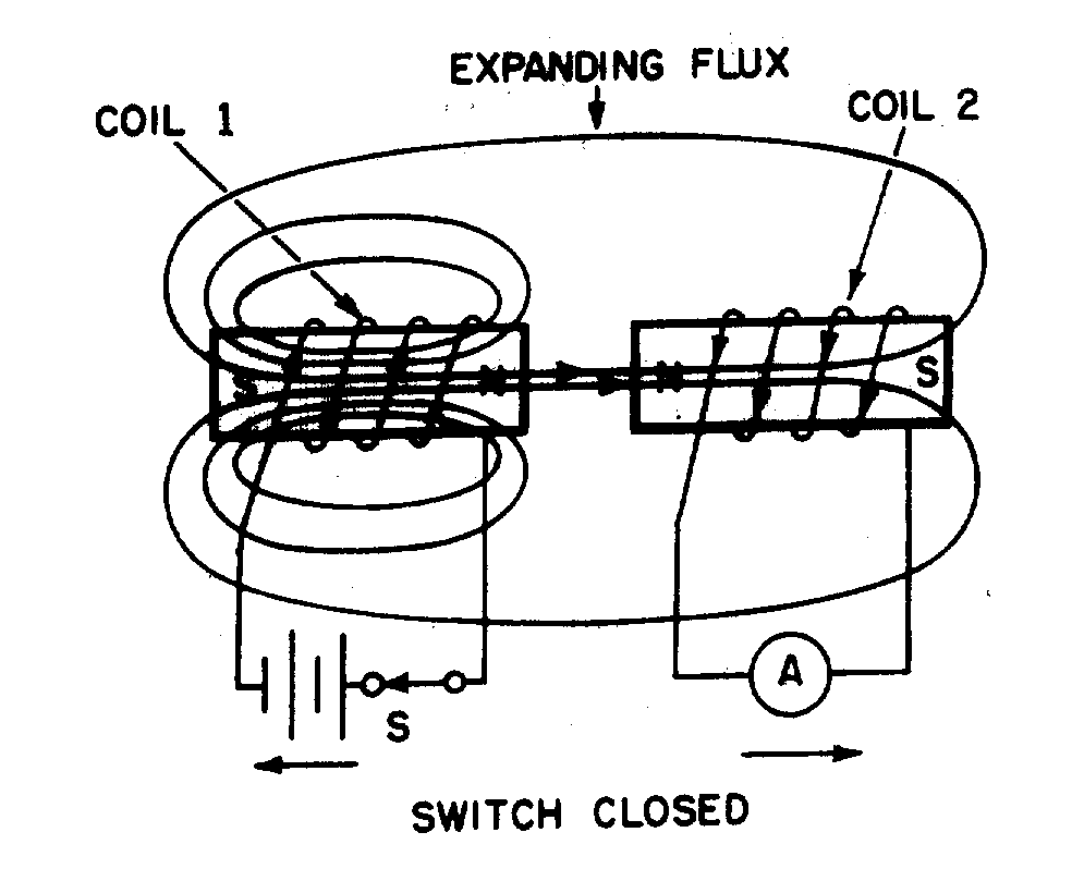
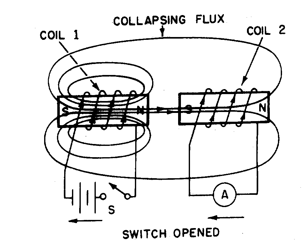
2-16
Two coils are placed close together as shown in figure 2-13. Coil 1 is connected to a battery through switch S, and coil 2 is connected to an ammeter (A). When switch S is closed as in figure 2-13(A), the current that flows in coil 1 sets up a magnetic field that links with coil 2, causing an induced voltage in coil 2 and a momentary deflection of the ammeter. When the current in coil 1 reaches a steady value, the ammeter returns to zero. If switch S is now opened as in figure 2-13(B), the ammeter (A) deflects momentarily in the opposite direction, indicating a momentary flow of current in the opposite direction in coil 2. This current in coil 2 is produced by the collapsing magnetic field of coil 1.
(A) (B)
Figure 2-13.—Mutual inductance.
Q12. Define mutual inductance.
FACTORS AFFECTING MUTUAL INDUCTANCE
The mutual inductance of two adjacent coils is dependent upon the physical dimensions of the two coils, the number of turns in each coil, the distance between the two coils, the relative positions of the axes of the two coils, and the permeability of the cores.
The COEFFICIENT OF COUPLING between two coils is equal to the ratio of the flux cutting one coil to the flux originated in the other coil. If the two coils are so positioned with respect to each other so that all of the flux of one coil cuts all of the turns of the other, the coils are said to have a unity coefficient of coupling. It is never exactly equal to unity (1), but it approaches this value in certain types of coupling devices. If all of the flux produced by one coil cuts only half the turns of the other coil, the coefficient of coupling is 0.5. The coefficient of coupling is designated by the letter K.
The mutual inductance between two coils, L1 and L2, is expressed in terms of the inductance of each coil and the coefficient of coupling K. As a formula:
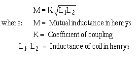
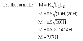
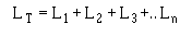
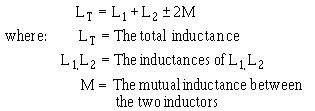
2-17
Example problem:
One 10-H coil and one 20-H coil are connected in series and are physically close enough to each other so that their coefficient of coupling is 0.5. What is the mutual inductance between the coils?
Q13. When are two circuits said to be coupled?
Q14. What is meant by the coefficient of coupling?
SERIES INDUCTORS WITHOUT MAGNETIC COUPLING
When inductors are well shielded or are located far enough apart from one another, the effect of mutual inductance is negligible. If there is no mutual inductance (magnetic coupling) and the inductors are connected in series, the total inductance is equal to the sum of the individual inductances. As a formula:
where LT is the total inductance; L 1, L2, L3 are the inductances of L1, L2, L3; and Ln means that any number (n) of inductors may be used. The inductances of inductors in series are added together like the resistances of resistors in series.
SERIES INDUCTORS WITH MAGNETIC COUPLING
When two inductors in series are so arranged that the field of one links the other, the combined inductance is determined as follows:
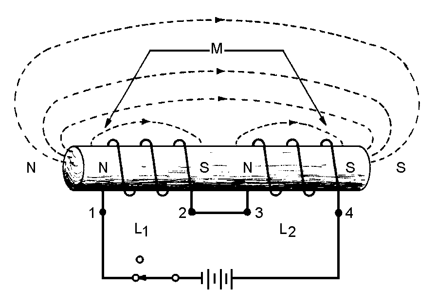
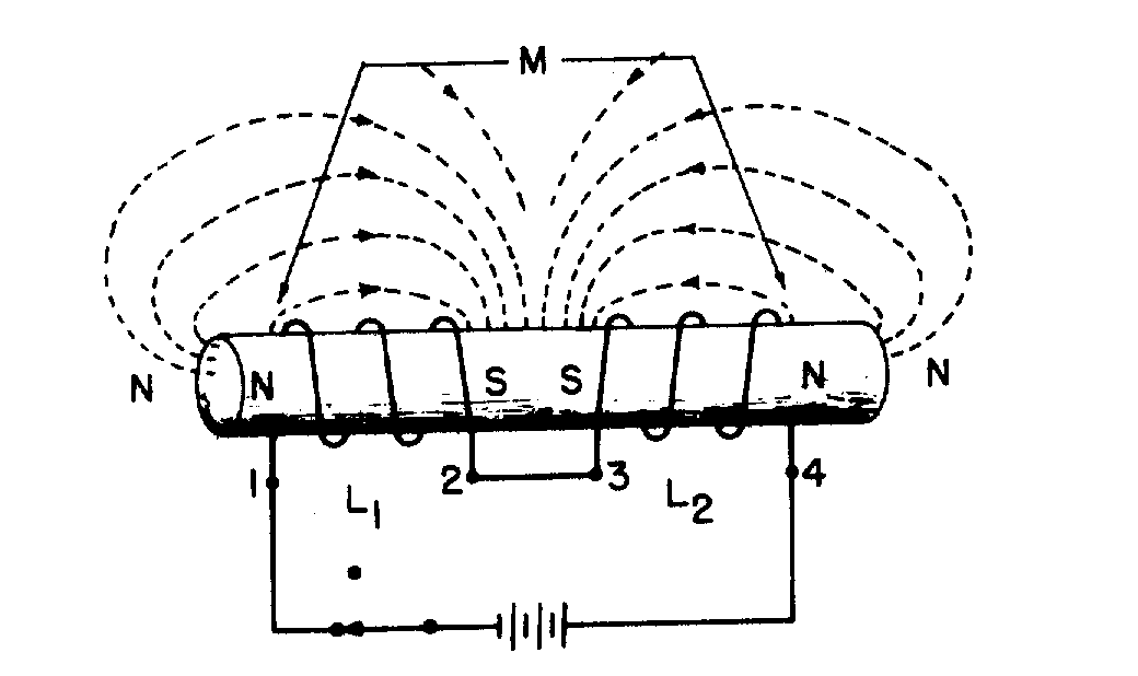
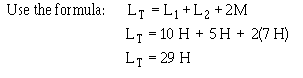
2-18
The plus sign is used with M when the magnetic fields of the two inductors are aiding each other, as shown in figure 2-14. The minus sign is used with M when the magnetic field of the two inductors oppose each other, as shown in figure 2-15. The factor 2M accounts for the influence of L1 on L2 and L2 on L1.
Figure 2-14.—Series inductors with aiding fields.
Figure 2-15.—Series inductors with opposing fields.
Example problem:
A 10-H coil is connected in series with a 5-H coil so the fields aid each other. Their mutual inductance is 7 H. What is the combined inductance of the coils?
Q15. Two series-connected 7-H inductors are adjacent to each other; their coefficient of coupling is
0.64. What is the value of M?
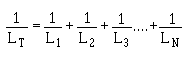
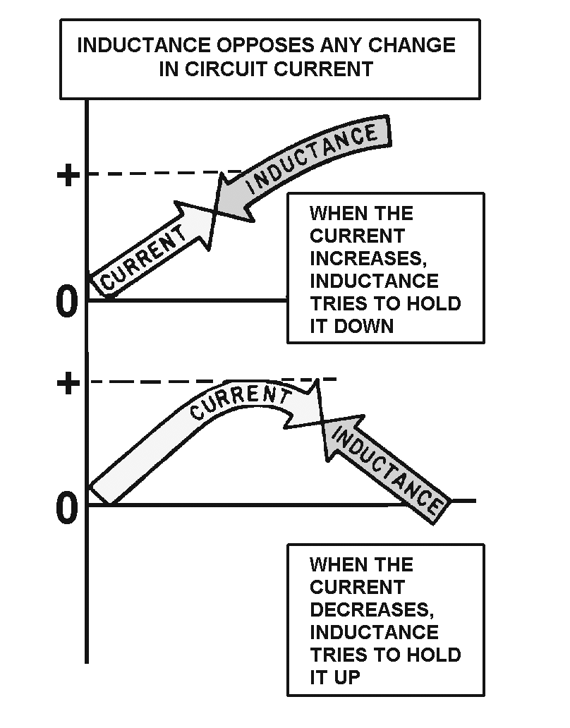
2-19
Q16. A circuit contains two series inductors aligned in such a way that their magnetic fields oppose each other. What formula should you use to compute total inductance in this circuit?
Q17. The magnetic fields of two coils are aiding each other. The inductance of the coils are 3 H and 5 H, respectively. The coils' mutual inductance is 5 H. What is their combined inductance?
PARALLEL INDUCTORS WITHOUT COUPLING
The total inductance (LT) of inductors in parallel is calculated in the same manner that the total resistance of resistors in parallel is calculated, provided the coefficient of coupling between the coils is zero. Expressed mathematically:
SUMMARY
The important points of this chapter are summarized below. Study this information before continuing, as this information will lay the foundation for later chapters.
INDUCTANCE—The characteristic of an electrical circuit that opposes a change in current. The reaction (opposition) is caused by the creation or destruction of a magnetic field. When current starts to flow, magnetic lines of force are created. These lines of force cut the conductor inducing a counter emf in a direction that opposes current.
2-20
SELF-INDUCTANCE—The process by which a circuit induces an emf into itself by its own moving magnetic field. All electrical circuits possess self-inductance. This opposition (inductance), however, only takes place when there is a change in current. Inductance does NOT oppose current, only a CHANGE in current. The property of inductance can be increased by forming the conductor into a loop. In a loop, the magnetic lines of force affect more of the conductor at one time. This increases the self- induced emf.
INDUCTANCE OF A COIL—The property of inductance can be further increased if the conductor is formed into a coil. Because a coil contains more loops, more of the conductor can be affected by the magnetic field. Inductors (coils) are classified according to core type. The core material is normally either air or soft iron.
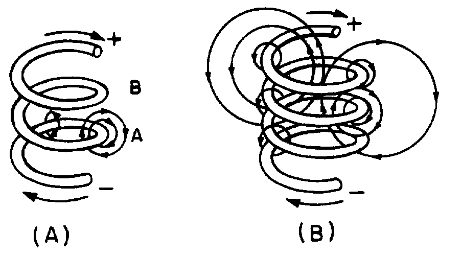
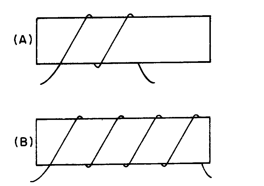
2-21
FACTORS AFFECTING COIL INDUCTANCE—The inductance of a coil is entirely dependent upon its physical construction. Some of the factors affecting the inductance are:
• The number of turns in the coil. Increasing the number of turns will increase the inductance.
• The coil diameter. The inductance increases directly as the cross-sectional area of the coil increases.
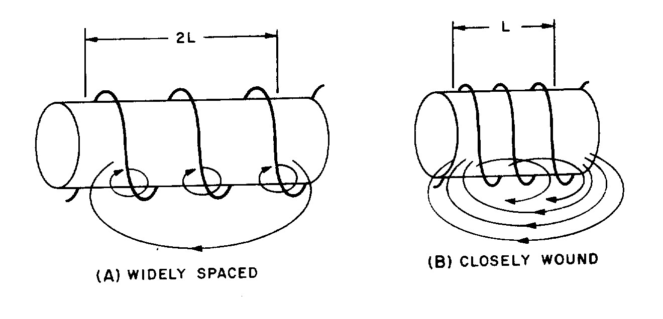
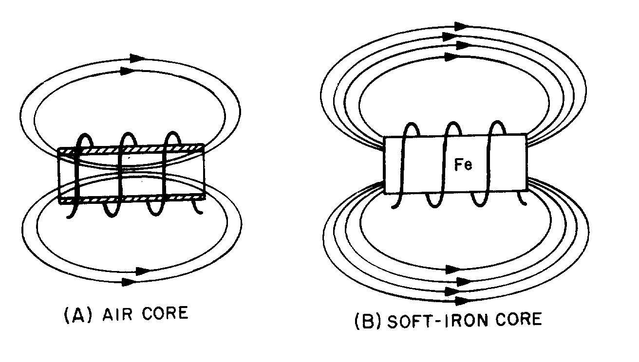
2-22
(A) (B)
• The length of the coil. When the length of the coil is increased while keeping the number of turns the same, the turn-spacing is increased. This decreases the inductance of the coil.
• The type of core material. Increasing the permeability of the core results in increasing the
inductance of the coil.
• Winding the coil in layers. The more layers used to form a coil, the greater effect the magnetic
field has on the conductor. By layering a coil, you can increase the inductance.
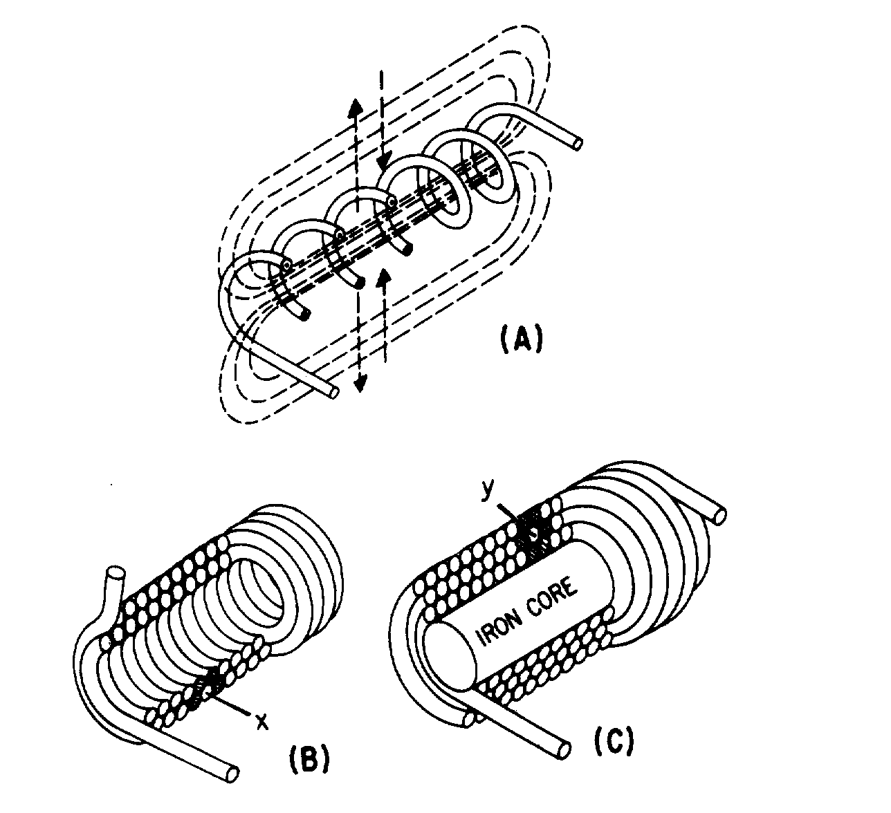
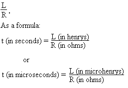
2-23
UNIT OF INDUCTANCE—Inductance (L) is measured in henrys (H). An inductor has an inductance of one henry (H) if an emf of one volt is induced in the inductor when the current through the inductor is changing at the rate of 1 ampere per second. Common units of inductance are henry (H), millihenry (mH) and the microhenry (µH).
GROWTH AND DECAY OF CURRENT IN AN LR CIRCUIT—The required for the current in an inductor to increase to 63.2 percent of the maximum current or to decrease to 36.8 percent of the maximum current is known as the time constant. The letter symbol for an LR time constant is L/R. As a formula:
2-24
The time constant of an LR circuit may also be defined as the time required for the current in the inductor to grow or decay to its final value if it continued to grow or decay at its initial rate. For all practical purposes, the current in the inductor reaches a maximum value in 5 "Time Constants" and decreases to zero in 5 "Time Constants".
POWER LOSSES IN AN INDUCTOR—Since an inductor (coil) contains a number turns of wire, and all wire has some resistance, the inductor has a certain amount of resistance. This resistance is usually very small and has a negligible effect on current. However, there are power losses in an inductor. The main power losses in an inductor are copper loss, hysteresis loss, and eddy-current loss. Copper loss can be calculated by multiplying the square of the current by the resistance of the wire in the coil (I2R). Hysteresis loss is due to power that is consumed in reversing the magnetic field of the core each time the current direction changes. Eddy-current loss is due to core heating caused by circulating currents induced in an iron core by the magnetic field of the coil.
MUTUAL INDUCTANCE—When two coils are located so that the flux from one coil cuts the turns of the other coil, the coils have mutual inductance. The amount of mutual inductance depends upon several factors: the relative position of the axes of the two coils; the permeability of the cores; the physical dimensions of the two coils; the number of turns in each coil, and the distance between the coils. The coefficient of coupling K specifies the amount of coupling between the coils. If all of the flux from one coil cuts all of the turns of the other coil, the coefficient of coupling K is 1 or unity. If none of the flux from one coil cuts the turns of the other coil, the coefficient of coupling is zero. The mutual inductance between two coils (L1 and L2) may be expressed mathematically as:
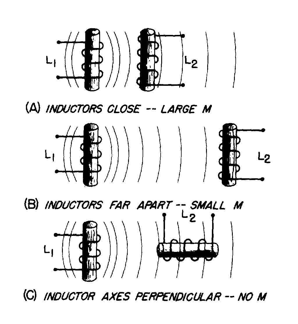
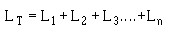
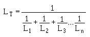
2-25
COMPUTING THE INDUCTANCE OF A CIRCUIT—When the total inductance of a circuit is computed, the individual inductive values are treated the same as resistance values. The inductances of inductors in series are added like the resistances of resistors in series. That is,
The inductances of inductors in parallel are combined mathematically like the resistances of resistors in parallel. That is,
Both of the above formulas are accurate, providing there is no mutual inductance between the inductors.
2-26
ANSWERS TO QUESTIONS Q1. THROUGH Q17.
A1. The henry, H.
A2. Magnetic field.
A3. Inductance is the property of a coil (or circuit) which opposes any CHANGE in current.
A4. Induced emf is the emf which appears across a conductor when there is relative motion between the conductor and a magnetic field; counter emf is the emf induced in a conductor that opposes the applied voltage.
A5. The induced emf in any circuit is in a direction to oppose the effect that produced it.
A6.
a. No effect.
b. Inductance opposes any change in the amplitude of current.
A7.
a.
1. The numbers of turns in a coil.
2. The type of material used in the core.
3. The diameter of the coil.
4. The coil length.
5. The number of layers of windings in the coil.
b. Increases inductance.
c. Increases inductance.
d. Decreases inductance.
e. Increases inductance.
f. Increases inductance.
A8.
a. Inductance causes a very large opposition to the flow of current when voltage is first applied to an LR circuit; resistance causes comparatively little opposition to current at that time.
b. Zero.
c. During current buildup, the voltage across the resistor gradually increases to the same voltage as the source voltage; and during current decay the voltage across the resistor gradually drops to zero

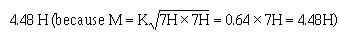
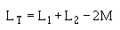
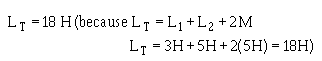
2-27
A9.
A10.
a. 1.71 amperes.
b. 5 time constants.
c. 2 time constants.
A11. Copper loss; hysteresis loss; eddy-current loss.
A12. Mutual inductance is the property existing between two coils so positioned that flux from one coil cuts the windings of the other coil.
A13. When they are arranged so that energy from one circuit is transferred to the other circuit.
A14. The ratio of the fines of force produced by one coil to the lines of force that link another coil. It is never greater than one.
A15.
A16.
A17.
3-1
CHAPTER 3
CAPACITANCE
LEARNING OBJECTIVES
Upon completion of this chapter you will be able to:
1. Define the terms "capacitor" and "capacitance."
2. State four characteristics of electrostatic lines of force.
3. State the effect that an electrostatic field has on a charged particle.
4. State the basic parts of a capacitor.
5. Define the term "farad".
6. State the mathematical relationship between a farad, a microfarad, and a picofarad.
7. State three factors that affect the value of capacitance.
8. Given the dielectric constant and the area of and the distance between the plates of a capacitor, solve for capacitance.
9. State two types of power losses associated with capacitors.
10. Define the term "working voltage" of a capacitor, and compute the working voltage of a capacitor.
11. State what happens to the electrons in a capacitor when the capacitor is charging and when it is discharging.
12. State the relationship between voltage and time in an RC circuit when the circuit is charging and discharging.
13. State the relationship between the voltage drop across a resistor and the source voltage in an RC circuit.
14. Given the component values of an RC circuit, compute the RC time constant.
15. Use the universal time constant chart to determine the value of an unknown capacitor in an RC circuit.
16. Calculate the value of total capacitance in a circuit containing capacitors of known value in series.
17. Calculate the value of total capacitance in a circuit containing capacitors of known value in parallel.
18. State the difference between different types of capacitors.
19. Determine the electrical values of capacitors using the color code.
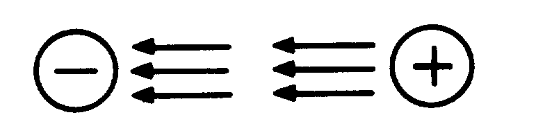
Figure 3-1.—Electrostatic field attracts two unlike charged particles.
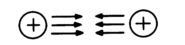
Figure 3-2.—Electrostatic field repels two like charged particles.
3-2
CAPACITANCE
In the previous chapter you learned that inductance is the property of a coil that causes electrical energy to be stored in a magnetic field about the coil. The energy is stored in such a way as to oppose any change in current. CAPACITANCE is similar to inductance because it also causes a storage of energy. A CAPACITOR is a device that stores electrical energy in an ELECTROSTATIC FIELD. The energy is stored in such a way as to oppose any change in voltage. Just how capacitance opposes a change in voltage is explained later in this chapter. However, it is first necessary to explain the principles of an electrostatic field as it is applied to capacitance.
Q1. Define the terms "capacitor" and "capacitance."
THE ELECTROSTATIC FIELD
You previously learned that opposite electrical charges attract each other while like electrical charges repel each other. The reason for this is the existence of an electrostatic field. Any charged particle is surrounded by invisible lines of force, called electrostatic lines of force. These lines of force have some interesting characteristics:
• They are polarized from positive to negative.
• They radiate from a charged particle in straight lines and do not form closed loops.
• They have the ability to pass through any known material.
• They have the ability to distort the orbits of tightly bound electrons.
Examine figure 3-1. This figure represents two unlike charges surrounded by their electrostatic field. Because an electrostatic field is polarized positive to negative, arrows are shown radiating away from the positive charge and toward the negative charge. Stated another way, the field from the positive charge is pushing, while the field from the negative charge is pulling. The effect of the field is to push and pull the unlike charges together.
In figure 3-2, two like charges are shown with their surrounding electrostatic field. The effect of the electrostatic field is to push the charges apart.

Figure 3-3.—Distortion of electron orbital paths due to electrostatic force.
3-3
If two unlike charges are placed on opposite sides of an atom whose outermost electrons cannot escape their orbits, the orbits of the electrons are distorted as shown in figure 3-3. Figure 3-3(A) shows the normal orbit. Part (B) of the figure shows the same orbit in the presence of charged particles. Since the electron is a negative charge, the positive charge attracts the electrons, pulling the electrons closer to the positive charge. The negative charge repels the electrons, pushing them further from the negative charge. It is this ability of an electrostatic field to attract and to repel charges that allows the capacitor to store energy.
Q2. State four characteristics of electrostatic lines of force. Q3. An electron moves into the electrostatic field between a positive charge and a negative charge.
Toward which charge will the electron move?
THE SIMPLE CAPACITOR
A simple capacitor consists of two metal plates separated by an insulating material called a dielectric, as illustrated in figure 3-4. Note that one plate is connected to the positive terminal of a battery; the other plate is connected through a closed switch (S1) to the negative terminal of the battery. Remember, an insulator is a material whose electrons cannot easily escape their orbits. Due to the battery voltage, plate A is charged positively and plate B is charged negatively. (How this happens is explained later in this chapter.) Thus an electrostatic field is set up between the positive and negative plates. The electrons on the negative plate (plate B) are attracted to the positive charges on the positive plate (plate A).
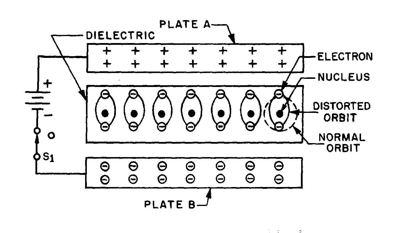
Figure 3-4.—Distortion of electron orbits in a dielectric.
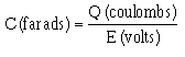
3-4
Notice that the orbits of the electrons in the dielectric material are distorted by the electrostatic field. The distortion occurs because the electrons in the dielectric are attracted to the top plate while being repelled from the bottom plate. When switch S1 is opened, the battery is removed from the circuit and the charge is retained by the capacitor. This occurs because the dielectric material is an insulator, and the electrons in the bottom plate (negative charge) have no path to reach the top plate (positive charge). The distorted orbits of the atoms of the dielectric plus the electrostatic force of attraction between the two plates hold the positive and negative charges in their original position. Thus, the energy which came from the battery is now stored in the electrostatic field of the capacitor. Two slightly different symbols for representing a capacitor are shown in figure 3-5. Notice that each symbol is composed of two plates separated by a space that represents the dielectric. The curved plate in (B) of the figure indicates the plate should be connected to a negative polarity.
(A)
(B) Figure 3-5.—Circuit symbols for capacitors.
Q4. What are the basic parts of a capacitor? THE FARAD
Capacitance is measured in units called FARADS. A one-farad capacitor stores one coulomb (a unit of charge (Q) equal to 6.28 × 10¹⁸ electrons) of charge when a potential of 1 volt is applied across the terminals of the capacitor. This can be expressed by the formula:

3-5
The farad is a very large unit of measurement of capacitance. For convenience, the microfarad ����������� �� � ��� ��� ���� ����������� �� �� ��� � ��� ����� ���� ���� �� ����� � �������� ���� or 1 × 10⁻⁶ farad, and 1.0 picofarad is equal to 0.000000000001 farad or 1.0 × 10⁻¹² farad. Capacitance is a physical property of the capacitor and does not depend on circuit characteristics of voltage, current, and resistance. A given capacitor always has the same value of capacitance (farads) in one circuit as in any other circuit in which it is connected.
Q5. Define the term "farad." Q6. What is the mathematical relationship between a farad, a microfarad, and a picofarad.
FACTORS AFFECTING THE VALUE OF CAPACITANCE
The value of capacitance of a capacitor depends on three factors:
• The area of the plates.
• The distance between the plates.
• The dielectric constant of the material between the plates.
PLATE AREA affects the value of capacitance in the same manner that the size of a container affects the amount of water that can be held by the container. A capacitor with the large plate area can store more charges than a capacitor with a small plate area. Simply stated, "the larger the plate area, the larger the capacitance".
The second factor affecting capacitance is the DISTANCE BETWEEN THE PLATES. Electrostatic lines of force are strongest when the charged particles that create them are close together. When the charged particles are moved further apart, the lines of force weaken, and the ability to store a charge decreases.
The third factor affecting capacitance is the DIELECTRIC CONSTANT of the insulating material between the plates of a capacitor. The various insulating materials used as the dielectric in a capacitor differ in their ability to respond to (pass) electrostatic lines of force. A dielectric material, or insulator, is rated as to its ability to respond to electrostatic lines of force in terms of a figure called the DIELECTRIC CONSTANT. A dielectric material with a high dielectric constant is a better insulator than a dielectric material with a low dielectric constant. Dielectric constants for some common materials are given in the following list:
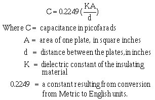
3-6
Material Constant
Vacuum 1.0000
Air 1.0006
Paraffin paper 3.5
Glass 5 to 10
Mica 3 to 6
Rubber 2.5 to 35
Wood 2.5 to 8
Glycerine (15ºC) 56 Petroleum 2
Pure water 81
Notice the dielectric constant for a vacuum. Since a vacuum is the standard of reference, it is assigned a constant of one. The dielectric constants of all materials are compared to that of a vacuum. Since the dielectric constant of air has been determined to be approximately the same as that of a vacuum, the dielectric constant of AIR is also considered to be equal to one.
The formula used to compute the value of capacitance is:
Example: Find the capacitance of a parallel plate capacitor with paraffin paper as the dielectric.
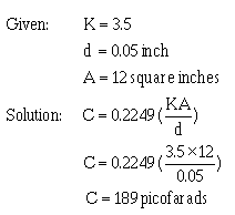
3-7
By examining the above formula you can see that capacitance varies directly as the dielectric constant and the area of the capacitor plates, and inversely as the distance between the plates.
Q7. State three factors that affect the capacitance of a capacitor. Q8. A parallel plate capacitor has the following values: K = 81, d = .025 inches, A = 6 square inches.
What is the capacitance of the capacitor?
VOLTAGE RATING OF CAPACITORS
In selecting or substituting a capacitor for use, consideration must be given to (1) the value of capacitance desired and (2) the amount of voltage to be applied across the capacitor. If the voltage applied across the capacitor is too great, the dielectric will break down and arcing will occur between the capacitor plates. When this happens the capacitor becomes a short-circuit and the flow of direct current through it can cause damage to other electronic parts. Each capacitor has a voltage rating (a working voltage) that should not be exceeded.
The working voltage of the capacitor is the maximum voltage that can be steadily applied without danger of breaking down the dielectric. The working voltage depends on the type of material used as the dielectric and on the thickness of the dialectic. (A high-voltage capacitor that has a thick dielectric must have a relatively large plate area in order to have the same capacitance as a similar low-voltage capacitor having a thin dielectric.) The working voltage also depends on the applied frequency because the losses, and the resultant heating effect, increase as the frequency increases.
A capacitor with a voltage rating of 500 volts dc cannot be safely subjected to an alternating voltage or a pulsating direct voltage having an effective value of 500 volts. Since an alternating voltage of 500 volts (rms) has a peak value of 707 volts, a capacitor to which it is applied should have a working voltage of at least 750 volts. In practice, a capacitor should be selected so that its working voltage is at least 50 percent greater than the highest effective voltage to be applied to it.
CAPACITOR LOSSES
Power loss in a capacitor may be attributed to dielectric hysteresis and dielectric leakage. Dielectric hysteresis may be defined as an effect in a dielectric material similar to the hysteresis found in a magnetic material. It is the result of changes in orientation of electron orbits in the dielectric because of the rapid reversals of the polarity of the line voltage. The amount of power loss due to dielectric hysteresis depends upon the type of dielectric used. A vacuum dielectric has the smallest power loss.
3-8
Dielectric leakage occurs in a capacitor as the result of LEAKAGE CURRENT through the dielectric. Normally it is assumed that the dielectric will effectively prevent the flow of current through the capacitor. Although the resistance of the dielectric is extremely high, a minute amount of current does flow. Ordinarily this current is so small that for all practical purposes it is ignored. However, if the leakage through the dielectric is abnormally high, there will be a rapid loss of charge and an overheating of the capacitor.
The power loss of a capacitor is determined by loss in the dielectric. If the loss is negligible and the capacitor returns the total charge to the circuit, it is considered to be a perfect capacitor with a power loss of zero.
Q9. Name two types of power losses associated with a capacitor. Q10.
a. Define the term "working voltage" of a capacitor. b. What should be the working voltage of a capacitor in a circuit that is operating at 600 volts?
CHARGING AND DISCHARGING A CAPACITOR
CHARGING
In order to better understand the action of a capacitor in conjunction with other components, the charge and discharge actions of a purely capacitive circuit are analyzed first. For ease of explanation the capacitor and voltage source shown in figure 3-6 are assumed to be perfect (no internal resistance), although this is impossible in practice.
In figure 3-6(A), an uncharged capacitor is shown connected to a four-position switch. With the switch in position 1 the circuit is open and no voltage is applied to the capacitor. Initially each plate of the capacitor is a neutral body and until a difference of potential is impressed across the capacitor, no electrostatic field can exist between the plates.
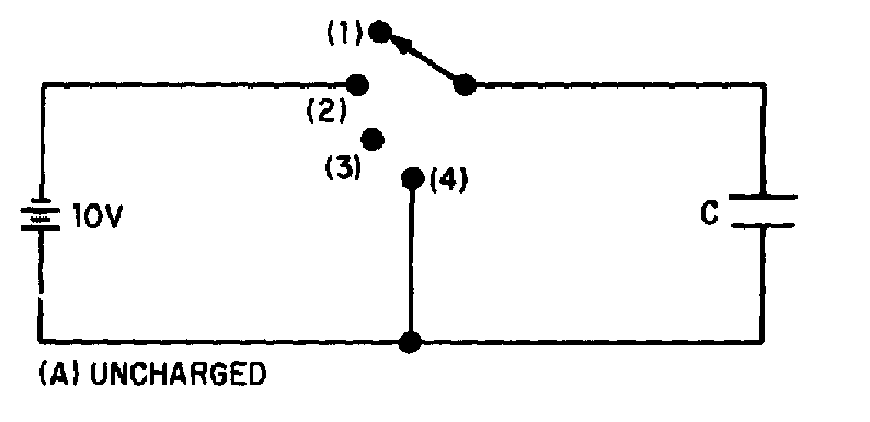
Figure 3-6.—Charging a capacitor.
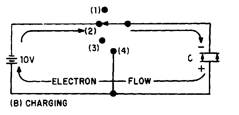
Figure 3-7.—Electron motion during charge.
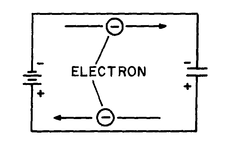
3-9
To CHARGE the capacitor, the switch must be thrown to position 2, which places the capacitor across the terminals of the battery. Under the assumed perfect conditions, the capacitor would reach full charge instantaneously. However, the charging action is spread out over a period of time in the following discussion so that a step-by-step analysis can be made.
At the instant the switch is thrown to position 2 (fig. 3-6(B)), a displacement of electrons occurs simultaneously in all parts of the circuit. This electron displacement is directed away from the negative terminal and toward the positive terminal of the source (the battery). A brief surge of current will flow as the capacitor charges.
If it were possible to analyze the motion of the individual electrons in this surge of charging current, the following action would be observed. See figure 3-7.
3-10
At the instant the switch is closed, the positive terminal of the battery extracts an electron from the bottom conductor. The negative terminal of the battery forces an electron into the top conductor. At this same instant an electron is forced into the top plate of the capacitor and another is pulled from the bottom plate. Thus, in every part of the circuit a clockwise DISPLACEMENT of electrons occurs simultaneously.
As electrons accumulate on the top plate of the capacitor and others depart from the bottom plate, a difference of potential develops across the capacitor. Each electron forced onto the top plate makes that plate more negative, while each electron removed from the bottom causes the bottom plate to become more positive. Notice that the polarity of the voltage which builds up across the capacitor is such as to oppose the source voltage. The source voltage (emf) forces current around the circuit of figure 3-7 in a clockwise direction. The emf developed across the capacitor, however, has a tendency to force the current in a counterclockwise direction, opposing the source emf. As the capacitor continues to charge, the voltage across the capacitor rises until it is equal to the source voltage. Once the capacitor voltage equals the source voltage, the two voltages balance one another and current ceases to flow in the circuit.
In studying the charging process of a capacitor, you must be aware that NO current flows THROUGH the capacitor. The material between the plates of the capacitor must be an insulator. However, to an observer stationed at the source or along one of the circuit conductors, the action has all the appearances of a true flow of current, even though the insulating material between the plates of the capacitor prevents the current from having a complete path. The current which appears to flow through a capacitor is called DISPLACEMENT CURRENT.
When a capacitor is fully charged and the source voltage is equaled by the counter electromotive force (cemf) across the capacitor, the electrostatic field between the plates of the capacitor is maximum. (Look again at figure 3-4.) Since the electrostatic field is maximum the energy stored in the dielectric is also maximum.
If the switch is now opened as shown in figure 3-8(A), the electrons on the upper plate are isolated. The electrons on the top plate are attracted to the charged bottom plate. Because the dielectric is an insulator, the electrons can not cross the dielectric to the bottom plate. The charges on both plates will be effectively trapped by the electrostatic field and the capacitor will remain charged indefinitely. You should note at this point that the insulating dielectric material in a practical capacitor is not perfect and small leakage current will flow through the dielectric. This current will eventually dissipate the charge. However, a high quality capacitor may hold its charge for a month or more.
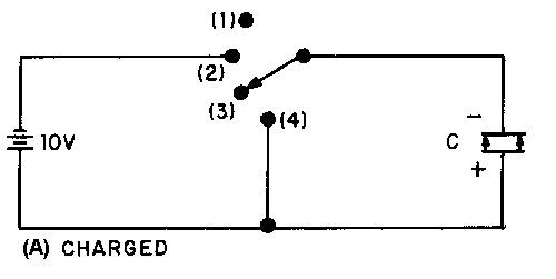
Figure 3-8.—Discharging a capacitor.
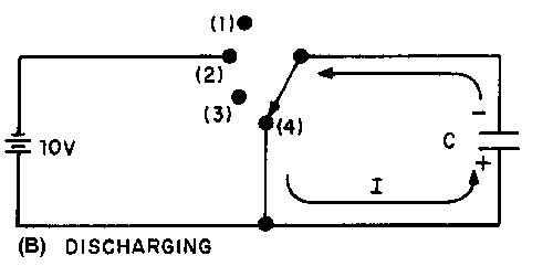
3-11
To review briefly, when a capacitor is connected across a voltage source, a surge of charging current flows. This charging current develops a cemf across the capacitor which opposes the applied voltage. When the capacitor is fully charged, the cemf is equal to the applied voltage and charging current ceases. At full charge, the electrostatic field between the plates is at maximum intensity and the energy stored in the dielectric is maximum. If the charged capacitor is disconnected from the source, the charge will be retained for some period of time. The length of time the charge is retained depends on the amount of leakage current present. Since electrical energy is stored in the capacitor, a charged capacitor can act as a source emf.
DISCHARGING
To DISCHARGE a capacitor, the charges on the two plates must be neutralized. This is accomplished by providing a conducting path between the two plates as shown in figure 3-8(B). With the switch in position (4) the excess electrons on the negative plate can flow to the positive plate and neutralize its charge. When the capacitor is discharged, the distorted orbits of the electrons in the dielectric return to their normal positions and the stored energy is returned to the circuit. It is important for you to note that a capacitor does not consume power. The energy the capacitor draws from the source is recovered when the capacitor is discharged.
Q11. State what happens to the electrons in a capacitor circuit when (a) the capacitor is charging and (b) the capacitor is discharging.
CHARGE AND DISCHARGE OF AN RC SERIES CIRCUIT
Ohm’s law states that the voltage across a resistance is equal to the current through the resistance times the value of the resistance. This means that a voltage is developed across a resistance ONLY WHEN CURRENT FLOWS through the resistance.

Figure 3-9.—Charge of an RC series circuit.
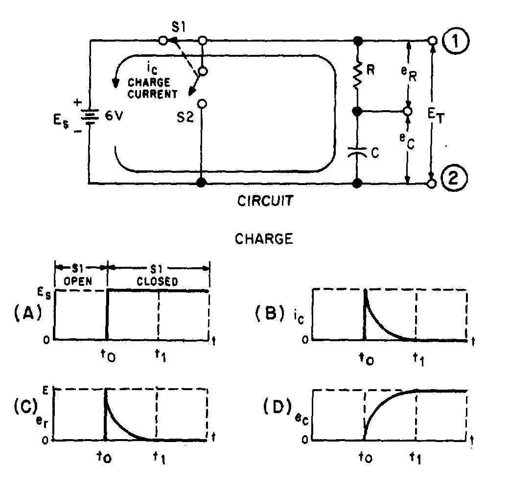
3-12
A capacitor is capable of storing or holding a charge of electrons. When uncharged, both plates of the capacitor contain essentially the same number of free electrons. When charged, one plate contains more free electrons than the other plate. The difference in the number of electrons is a measure of the charge on the capacitor. The accumulation of this charge builds up a voltage across the terminals of the capacitor, and the charge continues to increase until this voltage equals the applied voltage. The charge in a capacitor is related to the capacitance and voltage as follows:
in which Q is the charge in coulombs, C the capacitance in farads, and E the emf across the capacitor in volts.
CHARGE CYCLE
A voltage divider containing resistance and capacitance is connected in a circuit by means of a switch, as shown at the top of figure 3-9. Such a series arrangement is called an RC series circuit.
In explaining the charge and discharge cycles of an RC series circuit, the time interval from time t0 (time zero, when the switch is first closed) to time t1 (time one, when the capacitor reaches full charge or discharge potential) will be used. (Note that switches S1 and S2 move at the same time and can never both be closed at the same time.)
3-13
When switch S1 of the circuit in figure 3-9 is closed at t0, the source voltage (ES) is instantly felt across the entire circuit. Graph (A) of the figure shows an instantaneous rise at time t0 from zero to source voltage (ES = 6 volts). The total voltage can be measured across the circuit between points 1 and 2. Now look at graph (B) which represents the charging current in the capacitor (ic). At time t 0, charging current is MAXIMUM. As time elapses toward time t
1, there is a continuous decrease in current flowing into the capacitor. The decreasing flow is caused by the voltage buildup across the capacitor. At time t1, current flowing in the capacitor stops. At this time, the capacitor has reached full charge and has stored maximum energy in its electrostatic field. Graph (C) represents the voltage drop (e) across the resistor (R). The value of er is determined by the amount of current flowing through the resistor on its way to the capacitor. At time t0 the current flowing to the capacitor is maximum. Thus, the voltage drop across the resistor is maximum (E = IR). As time progresses toward time t1, the current flowing to the capacitor steadily decreases and causes the voltage developed across the resistor (R) to steadily decrease. When time t
1 is reached, current flowing to the capacitor is stopped and the voltage developed across the resistor has decreased to zero.
You should remember that capacitance opposes a change in voltage. This is shown by comparing graph (A) to graph (D). In graph (A) the voltage changed instantly from 0 volts to 6 volts across the circuit, while the voltage developed across the capacitor in graph (D) took the entire time interval from time to to time t1 to reach 6 volts. The reason for this is that in the first instant at time t0, maximum current flows through R and the entire circuit voltage is dropped across the resistor. The voltage impressed across the capacitor at t0 is zero volts. As time progresses toward t
1, the decreasing current causes progressively less voltage to be dropped across the resistor (R), and more voltage builds up across the capacitor (C). At time t1, the voltage felt across the capacitor is equal to the source voltage (6 volts), and the voltage dropped across the resistor (R) is equal to zero. This is the complete charge cycle of the capacitor.
As you may have noticed, the processes which take place in the time interval t0 to t1 in a series RC circuit are exactly opposite to those in a series LR circuit.
For your comparison, the important points of the charge cycle of RC and LR circuits are summarized in table 3-1.
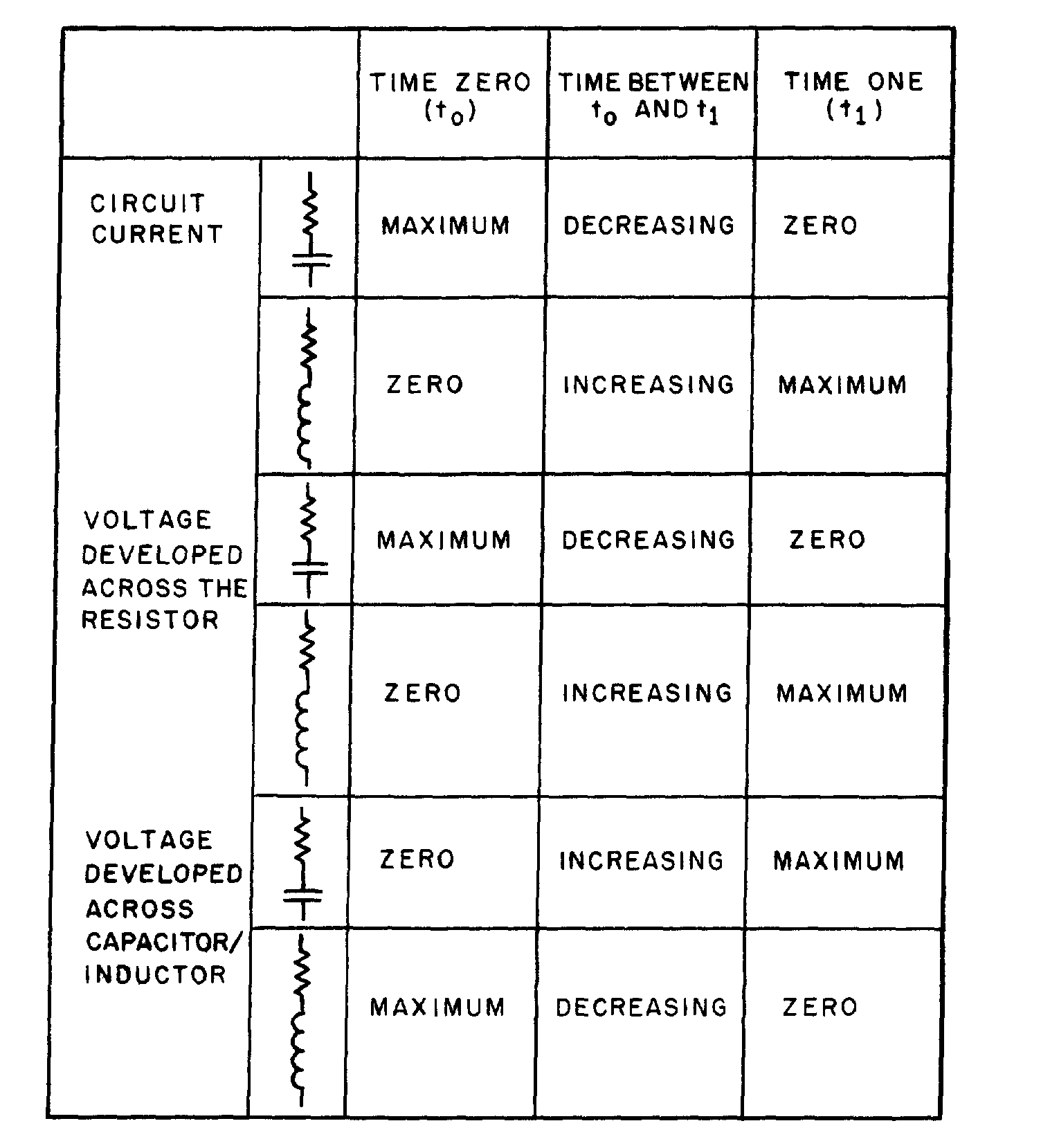
3-14
Table 3-1.—Summary of Capacitive and Inductive Characteristics
DISCHARGE CYCLE
In figure 3-10 at time t0, the capacitor is fully charged. When S1 is open and S2 closes, the capacitor discharge cycle starts. At the first instant, circuit voltage attempts to go from source potential (6 volts) to zero volts, as shown in graph (A). Remember, though, the capacitor during the charge cycle has stored energy in an electrostatic field.
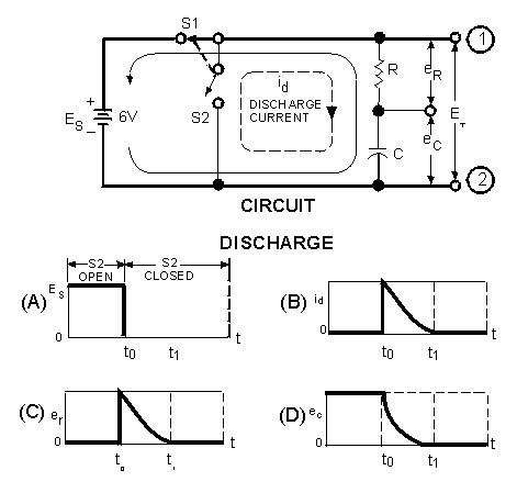
Figure 3-10.—Discharge of an RC Series circuit.
3-15
Because S2 is closed at the same time S1 is open, the stored energy of the capacitor now has a path for current to flow. At t0, discharge current (id) from the bottom plate of the capacitor through the resistor (R) to the top plate of the capacitor (C) is maximum. As time progresses toward t1, the discharge current steadily decreases until at time t1 it reaches zero, as shown in graph (B).
The discharge causes a corresponding voltage drop across the resistor as shown in graph (C). At time t0, the current through the resistor is maximum and the voltage drop (er) across the resistor is maximum. As the current through the resistor decreases, the voltage drop across the resistor decreases until at t1 it has reached a value of zero. Graph (D) shows the voltage across the capacitor (ec) during the discharge cycle. At time t0 the voltage is maximum and as time progresses toward time t1, the energy stored in the capacitor is depleted. At the same time the voltage across the resistor is decreasing, the voltage (e) across the capacitor is decreasing until at time t1 the voltage (ec) reaches zero.
By comparing graph (A) with graph (D) of figure 3-10, you can see the effect that capacitance has on a change in voltage. If the circuit had not contained a capacitor, the voltage would have ceased at the instant S1 was opened at time t0. Because the capacitor is in the circuit, voltage is applied to the circuit until the capacitor has discharged completely at t1. The effect of capacitance has been to oppose this change in voltage.
Q12. At what instant does the greatest voltage appear across the resistor in a series RC circuit when the capacitor is charging?
Q13. What is the voltage drop across the resistor in an RC charging circuit when the charge on the capacitor is equal to the battery voltage?
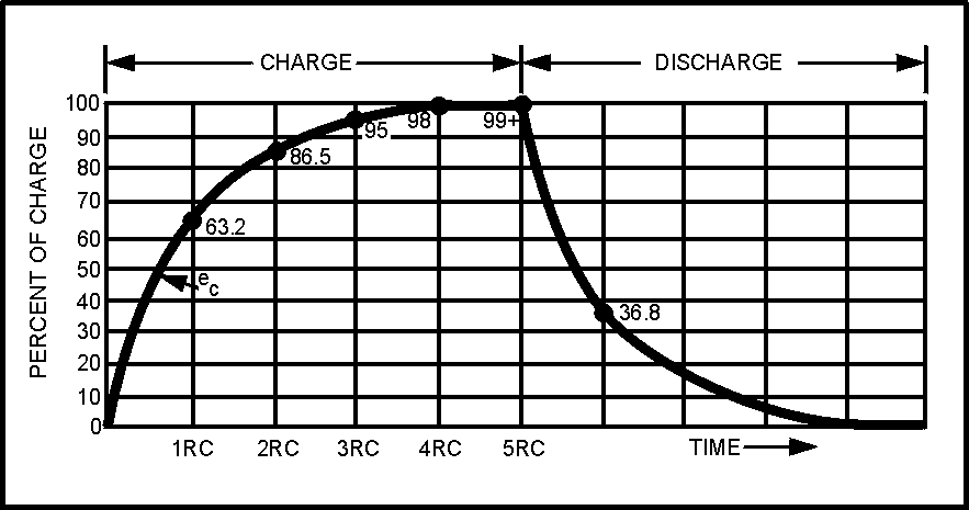
Figure 3-11.—RC time constant.
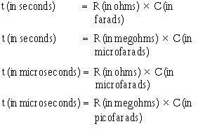
3-16
RC TIME CONSTANT
The time required to charge a capacitor to 63 percent (actually 63.2 percent) of full charge or to discharge it to 37 percent (actually 36.8 percent) of its initial voltage is known as the TIME CONSTANT (TC) of the circuit. The charge and discharge curves of a capacitor are shown in figure 3-11. Note that the charge curve is like the curve in figure 3-9, graph (D), and the discharge curve like the curve in figure 3-9, graph (B).
The value of the time constant in seconds is equal to the product of the circuit resistance in ohms and the circuit capacitance in farads. The value of one time constant is expressed mathematically as t = RC. Some forms of this formula used in calculating RC time constants are:
Q14. What is the RC time constant of a series RC circuit that contains a 12-megohm resistor and a 12-microfarad capacitor?
UNIVERSAL TIME CONSTANT CHART
Because the impressed voltage and the values of R and C or R and L in a circuit are usually known, a UNIVERSAL TIME CONSTANT CHART (fig. 3-12) can be used to find the time constant of the circuit. Curve A is a plot of both capacitor voltage during charge and inductor current during growth. Curve B is a plot of both capacitor voltage during discharge and inductor current during decay.
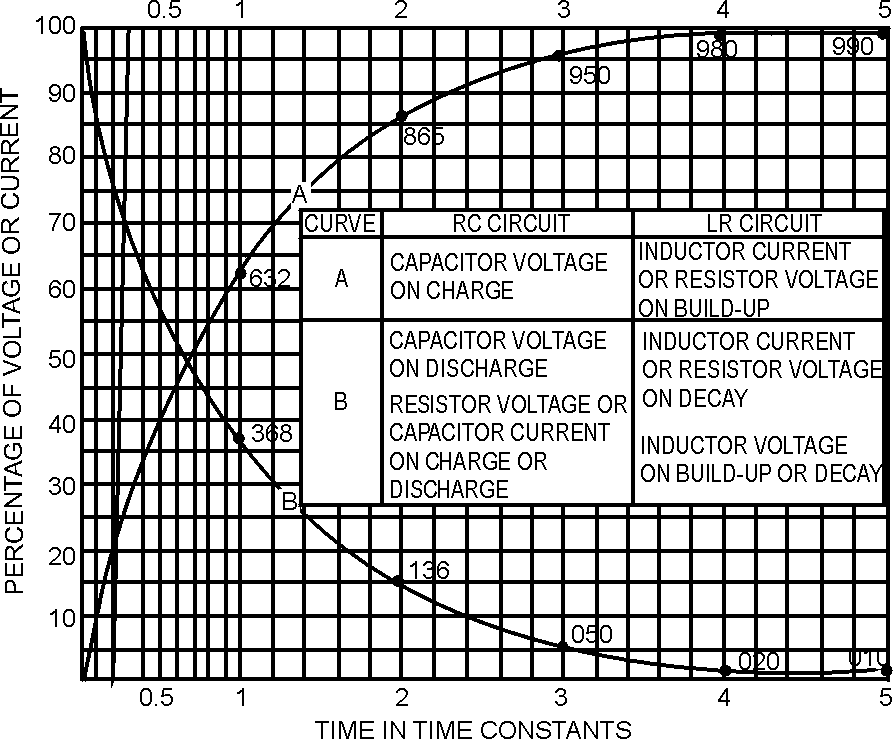
Figure 3-12.—Universal time constant chart for RC and RL circuit.
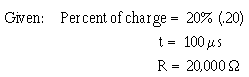
3-17
The time scale (horizontal scale) is graduated in terms of the RC or L/R time constants so that the curves may be used for any value of R and C or L and R. The voltage and current scales (vertical scales) are graduated in terms of percentage of the maximum voltage or current so that the curves may be used for any value of voltage or current. If the time constant and the initial or final voltage for the circuit in question are known, the voltages across the various parts of the circuit can be obtained from the curves for any time after the switch is closed, either on charge or discharge. The same reasoning is true of the current in the circuit.
The following problem illustrates how the universal time constant chart may be used.
An RC circuit is to be designed in which a capacitor (C) must charge to 20 percent (0.20) of the maximum charging voltage in 100 microseconds (0.0001 second). Because of other considerations, the resistor (R) must have a value of 20,000 ohms. What value of capacitance is needed?
Find: The capacitance of capacitor C.
Solution: Because the only values given are in units of time and resistance, a variation of the formula to find RC time is used:
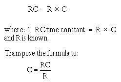
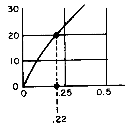
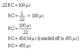
3-18
Find the value of RC by referring to the universal time constant chart in figure 3-12 and proceed as follows:
• Locate the 20 point on the vertical scale at the left side of the chart (percentage). • Follow the horizontal line from this point to intersect curve A.
• Follow an imaginary vertical line from the point of intersection on curve A downward to cross the RC scale at the bottom of the chart.
Note that the vertical line crosses the horizontal scale at about .22 RC as illustrated below:
The value selected from the graph means that a capacitor (including the one you are solving for) will reach twenty percent of full charge in twenty-two one hundredths (.22) of one RC time constant. Remember that it takes 100 µs for the capacitor to reach 20% of full charge. Since 100 µs is equal to .22 RC (twenty- two one-hundredths), then the time required to reach one RC time constant must be equal to:
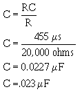
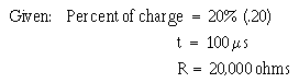
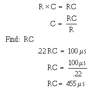
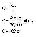
3-19
Now use the following formula to find C:
To summarize the above procedures, the problem and solution are shown below without the step by step explanation.
Transpose the RC time constant formula as follows:
Substitute the R and RC values into the formula:
The graphs shown in figure 3-11 and 3-12 are not entirely complete. That is, the charge or discharge (or the growth or decay) is not quite complete in 5 RC or 5 L/R time constants. However, when the values reach 0.99 of the maximum (corresponding to 5 RC or 5 L/R), the graphs may be considered accurate enough for all practical purposes.
Q15. A circuit is to be designed in which a capacitor must charge to 40 percent of the maximum charging voltage in 200 microseconds. The resistor to be used has a resistance of 40,000 ohms. What size capacitor must be used? (Use the universal time constant chart in figure 3-12.)
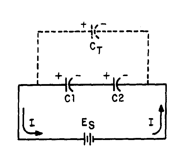
Figure 3-13.—Capacitors in series.
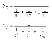
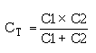
3-20
CAPACITORS IN SERIES AND PARALLEL
Capacitors may be connected in series or in parallel to obtain a resultant value which may be either the sum of the individual values (in parallel) or a value less than that of the smallest capacitance (in series). CAPACITORS IN SERIES
The overall effect of connecting capacitors in series is to move the plates of the capacitors further apart. This is shown in figure 3-13. Notice that the junction between C1 and C2 has both a negative and a positive charge. This causes the junction to be essentially neutral. The total capacitance of the circuit is developed between the left plate of C1 and the right plate of C2. Because these plates are farther apart, the total value of the capacitance in the circuit is decreased. Solving for the total capacitance (CT) of capacitors connected in series is similar to solving for the total resistance (RT) of resistors connected in parallel.
Note the similarity between the formulas for RT and CT:
If the circuit contains more than two capacitors, use the above formula. If the circuit contains only two capacitors, use the below formula:
Note: All values for CT, C1, C2, C3,... C n should be in farads. It should be evident from the above formulas that the total capacitance of capacitors in series is less than the capacitance of any of the individual capacitors.
Example: Determine the total capacitance of a series circuit containing three capacitors whose values are 0.01 µF, 0.25 µF, and 50,000 pF, respectively.
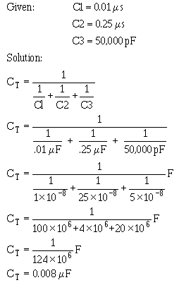
Figure 3-14.—Parallel capacitive circuit.
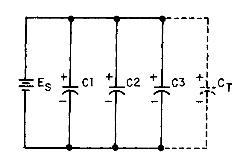
3-21
The total capacitance of 0.008µF is slightly smaller than the smallest capacitor (0.01µF). CAPACITORS IN PARALLEL
When capacitors are connected in parallel, one plate of each capacitor is connected directly to one terminal of the source, while the other plate of each capacitor is connected to the other terminal of the source. Figure 3-14 shows all the negative plates of the capacitors connected together, and all the positive plates connected together. C
T, therefore, appears as a capacitor with a plate area equal to the sum of all the individual plate areas. As previously mentioned, capacitance is a direct function of plate area. Connecting capacitors in parallel effectively increases plate area and thereby increases total capacitance.
For capacitors connected in parallel the total capacitance is the sum of all the individual capacitances. The total capacitance of the circuit may by calculated using the formula:
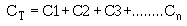
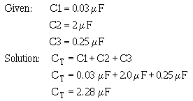
3-22
where all capacitances are in the same units.
Example: Determine the total capacitance in a parallel capacitive circuit containing three capacitors whose values are 0.03 µF, 2.0 µF, and 0.25 µF, respectively.
Q16. What is the total capacitance of a circuit that contains two capacitors (10 µF and 0.1 µF) wired together in series?
Q17. What is the total capacitance of a circuit in which four capacitors (10 µF, 21 µF, 0.1 µF and 2 µF) are connected in parallel?
FIXED CAPACITOR
A fixed capacitor is constructed in such manner that it possesses a fixed value of capacitance which cannot be adjusted. A fixed capacitor is classified according to the type of material used as its dielectric, such as paper, oil, mica, or electrolyte.
A PAPER CAPACITOR is made of flat thin strips of metal foil conductors that are separated by waxed paper (the dielectric material). Paper capacitors usually range in value from about 300 picofarads to about 4 microfarads. The working voltage of a paper capacitor rarely exceeds 600 volts. Paper capacitors are sealed with wax to prevent the harmful effects of moisture and to prevent corrosion and leakage.
Many different kinds of outer covering are used on paper capacitors, the simplest being a tubular cardboard covering. Some types of paper capacitors are encased in very hard plastic. These types are very rugged and can be used over a much wider temperature range than can the tubular cardboard type. Figure 3-15(A) shows the construction of a tubular paper capacitor; part 3-15(B) shows a completed cardboard- encased capacitor.
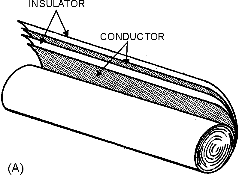
Figure 3-15.—Paper capacitor.
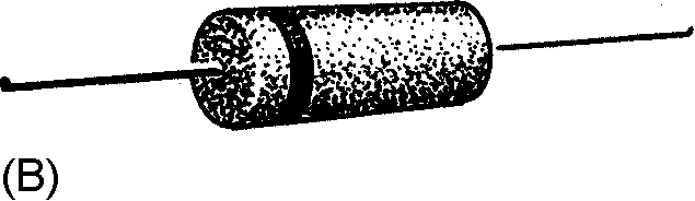
Figure 3-16.—Typical mica capacitors.
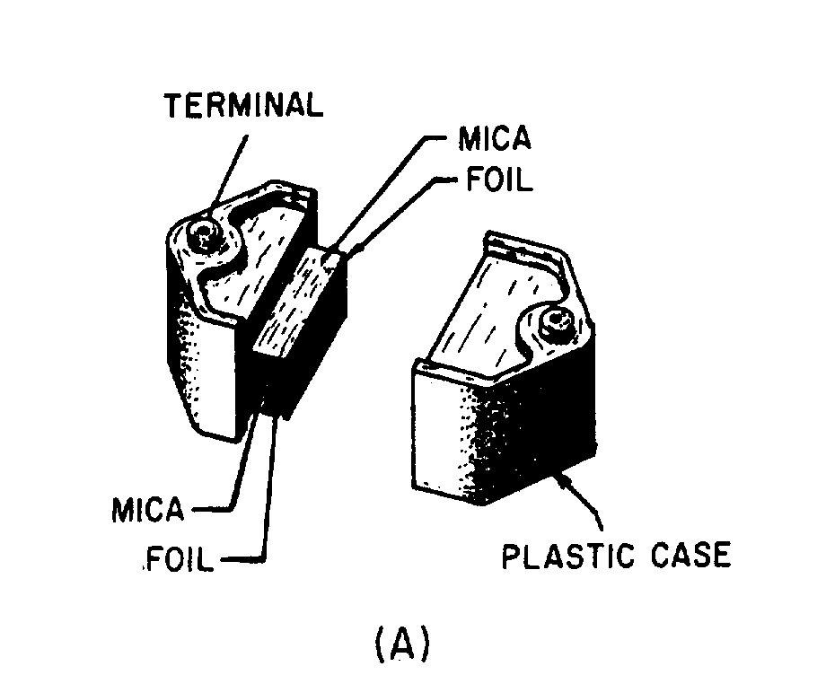
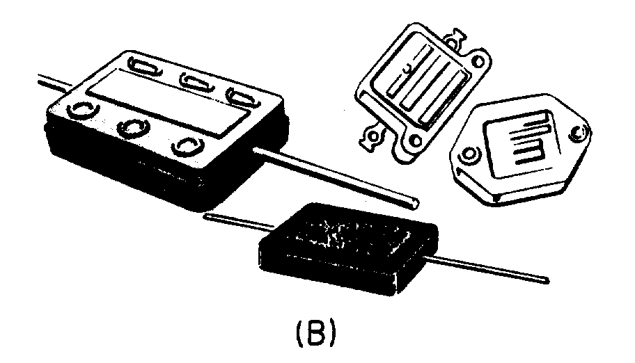
3-23
A MICA CAPACITOR is made of metal foil plates that are separated by sheets of mica (the dielectric). The whole assembly is encased in molded plastic. Figure 3-16(A) shows a cut-away view of a mica capacitor. Because the capacitor parts are molded into a plastic case, corrosion and damage to the plates and dielectric are prevented. In addition, the molded plastic case makes the capacitor mechanically stronger. Various types of terminals are used on mica capacitors to connect them into circuits. These terminals are also molded into the plastic case.
Mica is an excellent dielectric and can withstand a higher voltage than can a paper dielectric of the same thickness. Common values of mica capacitors range from approximately 50 picofarads to 0.02 microfarad. Some different shapes of mica capacitors are shown in figure 3-16(B).
A CERAMIC CAPACITOR is so named because it contains a ceramic dielectric. One type of ceramic capacitor uses a hollow ceramic cylinder as both the form on which to construct the capacitor and as the dielectric material. The plates consist of thin films of metal deposited on the ceramic cylinder.
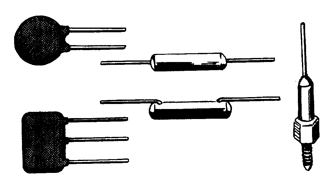
Figure 3-17.—Ceramic capacitors.
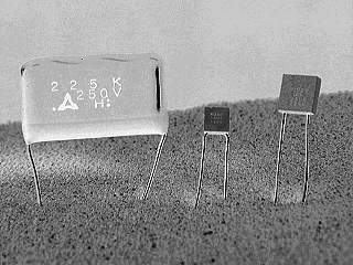
3-24
A second type of ceramic capacitor is manufactured in the shape of a disk. After leads are attached to each side of the capacitor, the capacitor is completely covered with an insulating moisture-proof coating. Ceramic capacitors usually range in value from 1 picofarad to 0.01 microfarad and may be used with voltages as high as 30,000 volts. Some different shapes of ceramic capacitors are shown in figure 3-17.
Examples of ceramic capacitors.
An ELECTROLYTIC CAPACITOR is used where a large amount of capacitance is required. As the name implies, an electrolytic capacitor contains an electrolyte. This electrolyte can be in the form of a liquid (wet electrolytic capacitor). The wet electrolytic capacitor is no longer in popular use due to the care needed to prevent spilling of the electrolyte.
A dry electrolytic capacitor consists essentially of two metal plates separated by the electrolyte. In most cases the capacitor is housed in a cylindrical aluminum container which acts as the negative terminal of the capacitor (see fig. 3-18). The positive terminal (or terminals if the capacitor is of the multisection type) is a lug (or lugs) on the bottom end of the container. The capacitance value(s) and the voltage rating of the capacitor are generally printed on the side of the aluminum case.
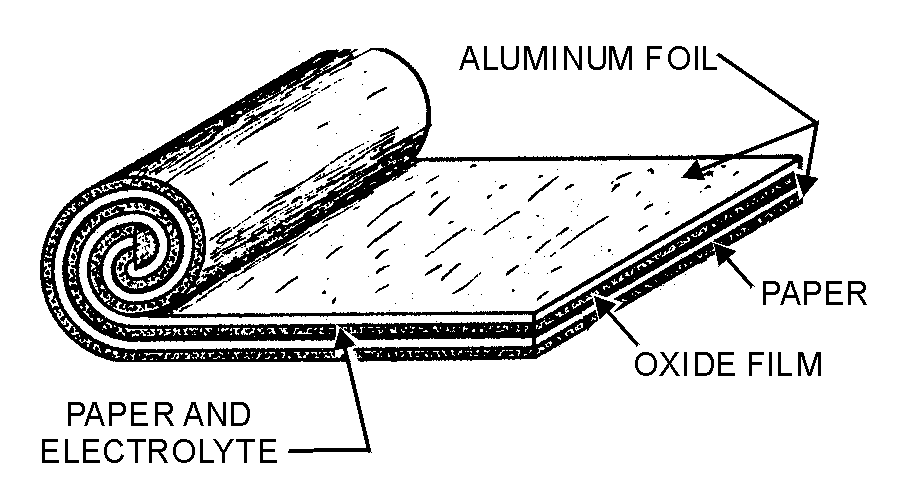
Figure 3-18.—Construction of an electrolytic capacitor.
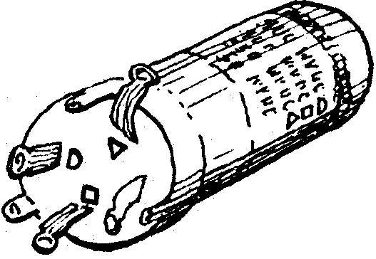
3-25
An example of a multisection electrolytic capacitor is illustrated in figure 3-18(B). The four lugs at the end of the cylindrical aluminum container indicates that four electrolytic capacitors are enclosed in the can. Each section of the capacitor is electrically independent of the other sections. It is possible for one section to be defective while the other sections are still good. The can is the common negative connection to the four capacitors. Separate terminals are provided for the positive plates of the capacitors. Each capacitor is identified by an embossed mark adjacent to the lugs, as shown in figure 3-18(B). Note the identifying marks used on the electrolytic capacitor are the half moon, the triangle, the square, and no embossed mark. By looking at the bottom of the container and the identifying sheet pasted to the side of the container, you can easily identify the value of each section.
Internally, the electrolytic capacitor is constructed similarly to the paper capacitor. The positive plate consists of aluminum foil covered with an extremely thin film of oxide. This thin oxide film (which is formed by an electrochemical process) acts as the dielectric of the capacitor. Next to and in contact with the oxide is a strip of paper or gauze which has been impregnated with a paste-like electrolyte. The electrolyte acts as the negative plate of the capacitor. A second strip of aluminum foil is then placed against the electrolyte to provide electrical contact to the negative electrode (the electrolyte). When the three layers are in place they are rolled up into a cylinder as shown in figure 3-18(A).
An electrolytic capacitor has two primary disadvantages compared to a paper capacitor in that the electrolytic type is POLARIZED and has a LOW LEAKAGE RESISTANCE. This means that should the positive plate be accidentally connected to the negative terminal of the source, the thin oxide film dielectric will dissolve and the capacitor will become a conductor (i.e., it will short). The polarity of the terminals is normally marked on the case of the capacitor. Since an electrolytic capacitor is polarity sensitive, its use is ordinarily restricted to a dc circuit or to a circuit where a small ac voltage is superimposed on a dc voltage. Special electrolytic capacitors are available for certain ac applications, such as a motor starting capacitor. Dry electrolytic capacitors vary in size from about 4 microfarads to several thousand microfarads and have a working voltage of approximately 500 volts.
The type of dielectric used and its thickness govern the amount of voltage that can safely be applied to the electrolytic capacitor. If the voltage applied to the capacitor is high enough to cause the atoms of the
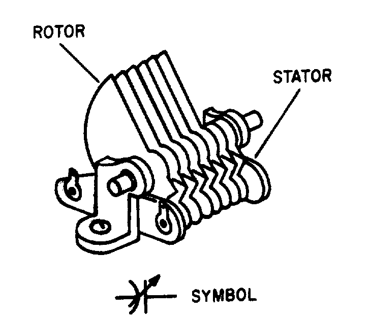
Figure 3-19.—Rotor-stator type variable capacitor.
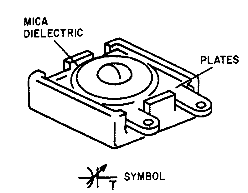
Figure 3-20.—Trimmer capacitor.
3-26
dielectric material to become ionized, arcing between the plates will occur. In most other types of capacitors, arcing will destroy the capacitor. However, an electrolytic capacitor has the ability to be self-healing. If the arcing is small, the electrolytic will regenerate itself. If the arcing is too large, the capacitor will not self-heal and will become defective.
OIL CAPACITORS are often used in high-power electronic equipment. An oil-filled capacitor is nothing more than a paper capacitor that is immersed in oil. Since oil impregnated paper has a high dielectric constant, it can be used in the production of capacitors having a high capacitance value. Many capacitors will use oil with another dielectric material to prevent arcing between the plates. If arcing should occur between the plates of an oil-filled capacitor, the oil will tend to reseal the hole caused by the arcing. Such a capacitor is referred to as a SELF-HEALING capacitor.
VARIABLE CAPACITOR
A variable capacitor is constructed in such manner that its value of capacitance can be varied. A typical variable capacitor (adjustable capacitor) is the rotor-stator type. It consists of two sets of metal plates arranged so that the rotor plates move between the stator plates. Air is the dielectric. As the position of the rotor is changed, the capacitance value is likewise changed. This type of capacitor is used for tuning most radio receivers. Its physical appearance and its symbol are shown in figure 3-19.
Another type of variable capacitor (trimmer capacitor) and its symbol are shown in figure 3-20. This capacitor consists of two plates separated by a sheet of mica. A screw adjustment is used to vary the distance between the plates, thereby changing the capacitance.
3-27
Q18. a. An oxide-film dielectric is used in what type of capacitor?
b. A screw adjustment is used to vary the distance between the plates of what type of capacitor? COLOR CODES FOR CAPACITORS
Although the capacitance value may be printed on the body of a capacitor, it may also be indicated by a color code. The color code used to represent capacitance values is similar to that used to represent resistance values. The color codes currently in use are the Joint Army-Navy (JAN) code and the Radio Manufacturers’ Association (RMA) code.
For each of these codes, colored dots or bands are used to indicate the value of the capacitor. A mica capacitor, it should be noted, may be marked with either three dots or six dots. Both the three- and the six- dot codes are similar, but the six-dot code contains more information about electrical ratings of the capacitor, such as working voltage and temperature coefficient.
The capacitor shown in figure 3-21 represents either a mica capacitor or a molded paper capacitor. To determine the type and value of the capacitor, hold the capacitor so that the three arrows point left to right (>). The first dot at the base of the arrow sequence (the left-most dot) represents the capacitor TYPE. This dot is either black, white, silver, or the same color as the capacitor body. Mica is represented by a black or white dot and paper by a silver dot or dot having the same color as the body of the capacitor. The two dots to the immediate right of the type dot indicate the first and second digits of the capacitance value. The dot at the bottom right represents the multiplier to be used. The multiplier represents picofarads. The dot in the bottom center indicates the tolerance value of the capacitor.
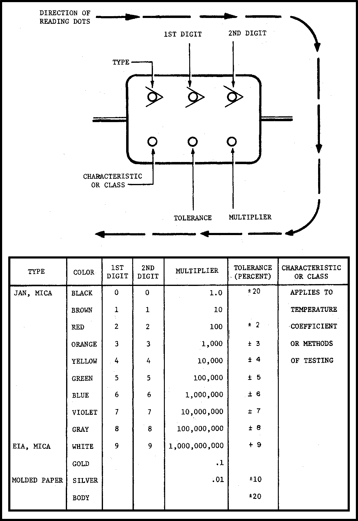
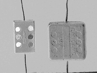
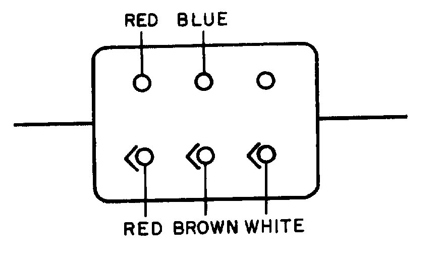
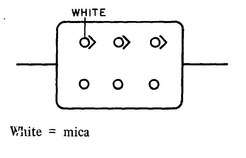
3-29
Example of mica capacitors.
Example of mica capacitors.
To read the capacitor color code on the above capacitor:
1. Hold the capacitor so the arrows point left to right.
2. Read the first dot.
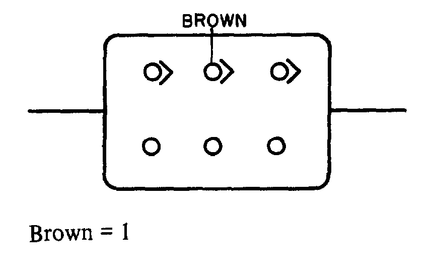
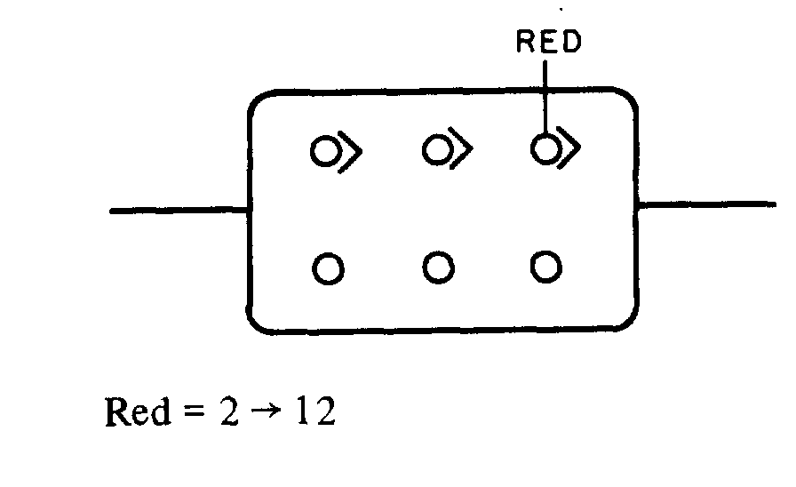
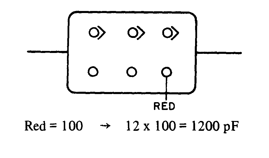
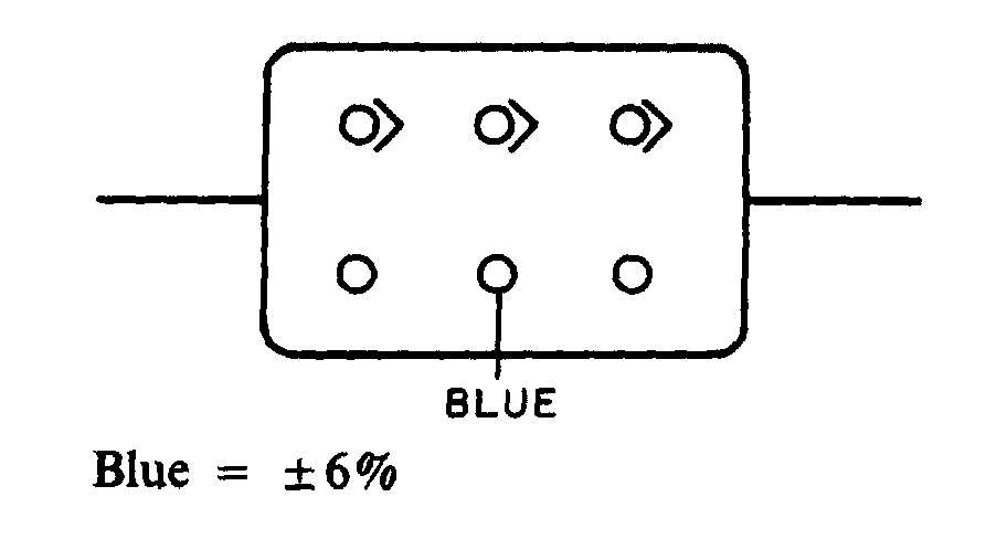
3-30
3. Read the first digit dot.
4. Read the second digit dot and apply it to the first digit.
5. Read the multiplier dot and multiply the first two digits by multiplier. (Remember that the multiplier is in picofarads).
6. Lastly, read the tolerance dot.
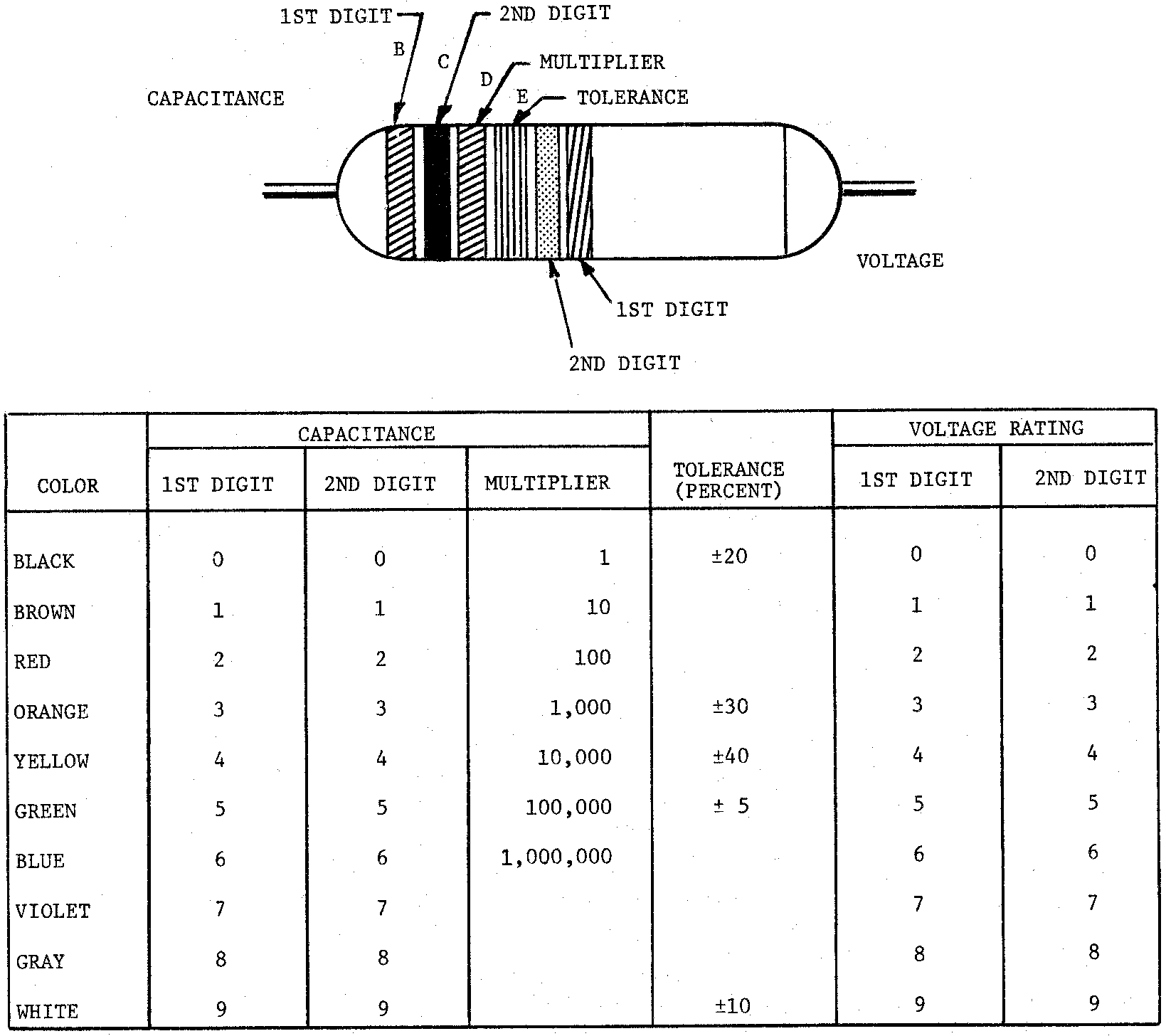
Figure 3-22.—6-band color code for tubular paper dielectric capacitors.
3-31
According to the above coding, the capacitor is a mica capacitor whose capacitance is 1200 pF with a tolerance of ±6%.
The capacitor shown in figure 3-22 is a tubular capacitor. Because this type of capacitor always has a paper dielectric, the type code is omitted. To read the code, hold the capacitor so the band closest to the end is on the left side; then read left to right. The last two bands (the fifth and sixth bands from the left) represent the voltage rating of the capacitor. This means that if a capacitor is coded red, red, red, yellow, yellow, yellow, it has the following digit values:
red = 2
red = 2
red = × 100 pF
yellow = �40%
yellow = 4
yellow = 4
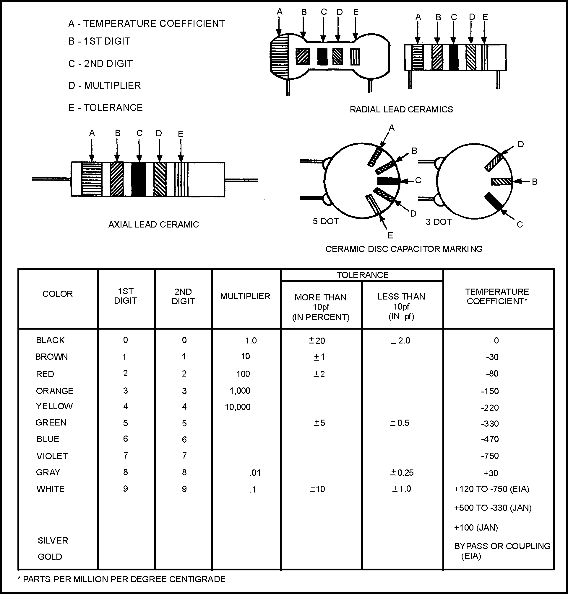
Figure 3-23.—Ceramic capacitor color code.
3-32
The six digits indicate a capacitance of 2200 pF with a ±40 percent tolerance and a working voltage of 44 volts.
The ceramic capacitor is color coded as shown in figure 3-23 and the mica capacitor as shown in figure 3-24. Notice that this type of mica capacitor differs from the one shown in figure 3-21 in that the arrow is solid instead of broken. This type of mica capacitor is read in the same manner as the one shown in figure 3-21, with one exception: the first dot indicates the first digit. (Note: Because this type of capacitor is always mica, there is no need for a type dot.)
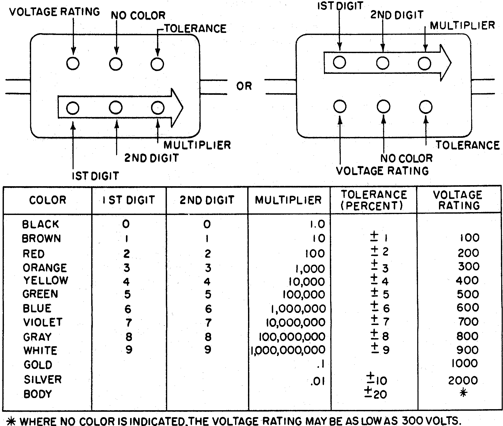
Figure 3-24.—Mica capacitor color code.
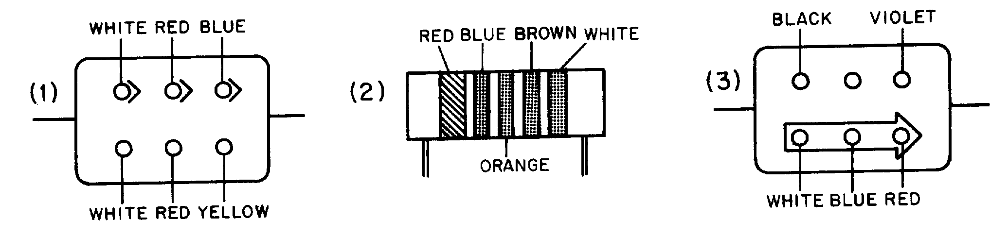
3-33
Q19. Examine the three capacitors shown below. What is the capacitance of each?
SUMMARY
Before going on to the next chapter, study the below summary to be sure that you understand the important points of this chapter.
THE ELECTROSTATIC FIELD—When a charged body is brought close to another charged body, the bodies either attract or repel one another. (If the charges are alike they repel; if the charges are opposite they attract). The field that causes this effect is called the ELECTROSTATIC FIELD. The amount by which two charges attract or repel each other depends upon the size of the charges and the distance between the charges. The electrostatic field (force between two charged bodies) may be represented by lines of force
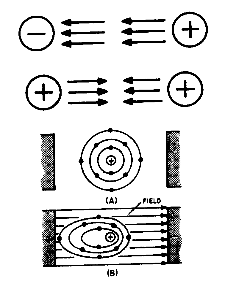
3-34
drawn perpendicular to the charged surfaces. If an electron is placed in the field, it will move toward the positive charge.
CAPACITANCE—Capacitance is the property of a circuit which OPPOSES any CHANGE in the circuit VOLTAGE. The effect of capacitance may be seen in any circuit where the voltage is changing. Capacitance is usually defined as the ability of a circuit to store electrical energy. This energy is stored in an electrostatic field. The device used in an electrical circuit to store this charge (energy) is called a CAPACITOR. The basic unit of measurement of capacitance is the FARAD (F). A one-farad capacitor will store one coulomb of charge (energy) when a potential of one volt is applied across the capacitor plates. The ���� �� �� �� �� ���� ����� ���� � ������������ � �� ��������� ����� ��� ��� ���� ���� � �� � ��� picofarad (pF).
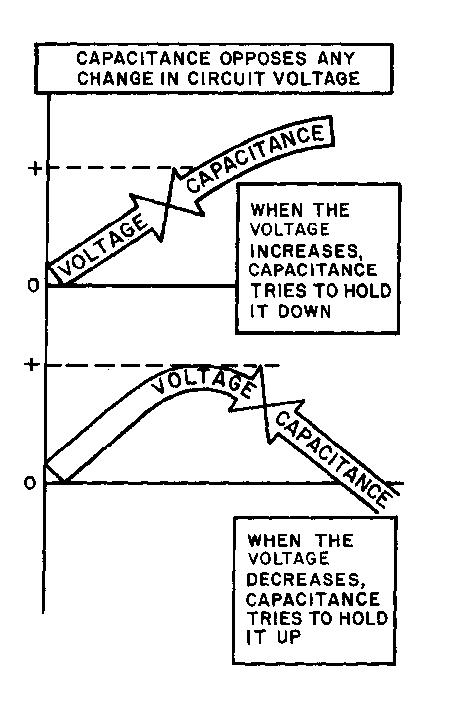
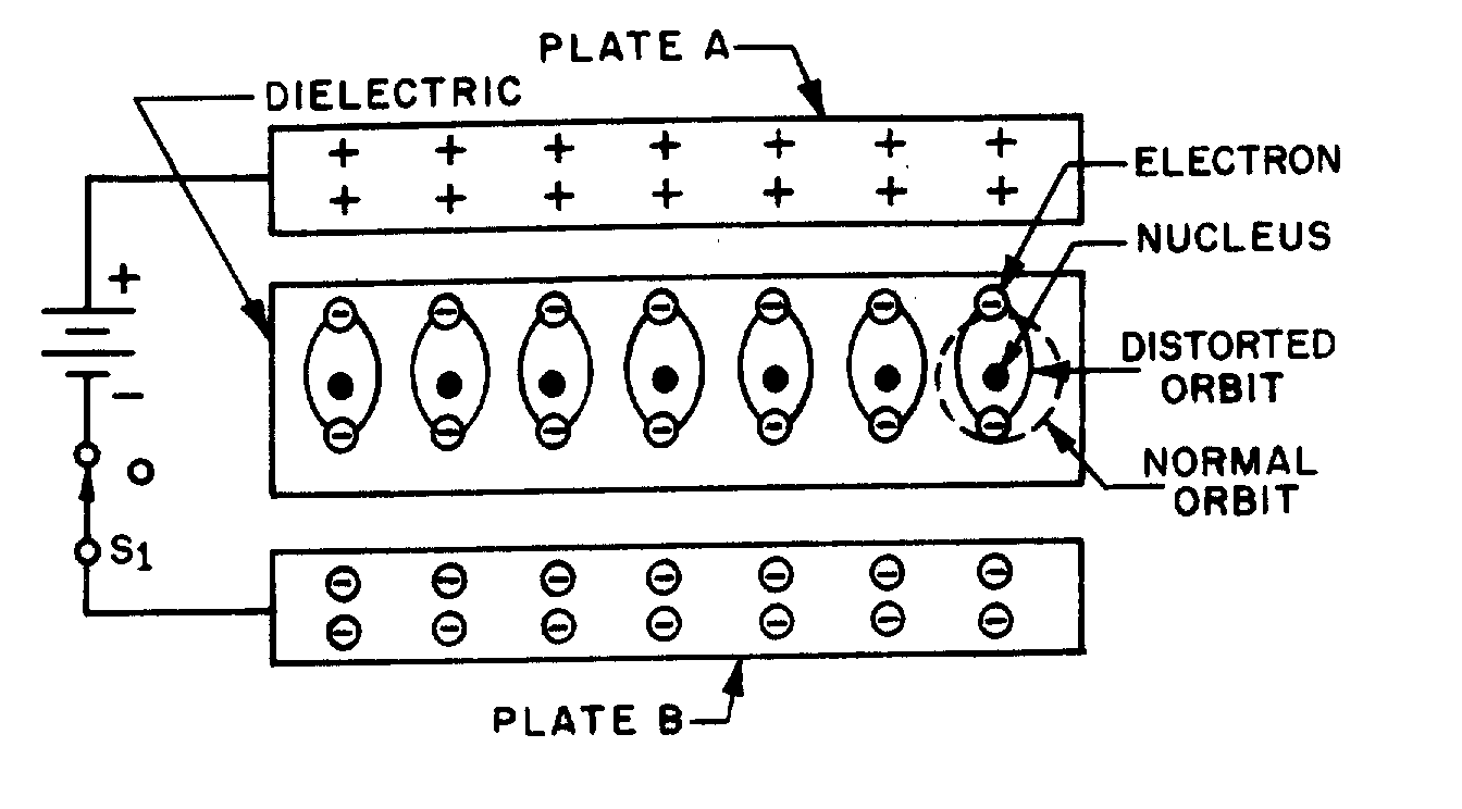
3-35
CAPACITOR—A capacitor is a physical device consisting of two pieces of conducting material separated by an insulating material. This insulating material is referred to as the DIELECTRIC. Because the dielectric is an insulator, NO current flows through the capacitor. If the dielectric breaks down and becomes a conductor, the capacitor can no longer hold a charge and is useless. The ability of a dielectric to hold a charge without breaking down is referred to as the dielectric strength. The measure of the ability of the dielectric material to store energy is called the dielectric constant. The dielectric constant is a relative value based on 1.0 for a vacuum.
CAPACITORS IN A DC CIRCUIT—When a capacitor is connected to the terminals of a battery, each plate of the capacitor becomes charged. The plate connected to the positive terminal loses electrons. Because this plate has a lack of electrons, it assumes a positive charge. The plate connected to the negative terminal gains electrons. Because the plate has an excess of electrons, it assumes a negative charge. This process continues until the charge across the plates equals the applied voltage. At this point current ceases to flow in the circuit. As long as nothing changes in the circuit, the capacitor will hold its charge and there will be no current in any part of the circuit. If the leads of the capacitor are now shorted together, current again
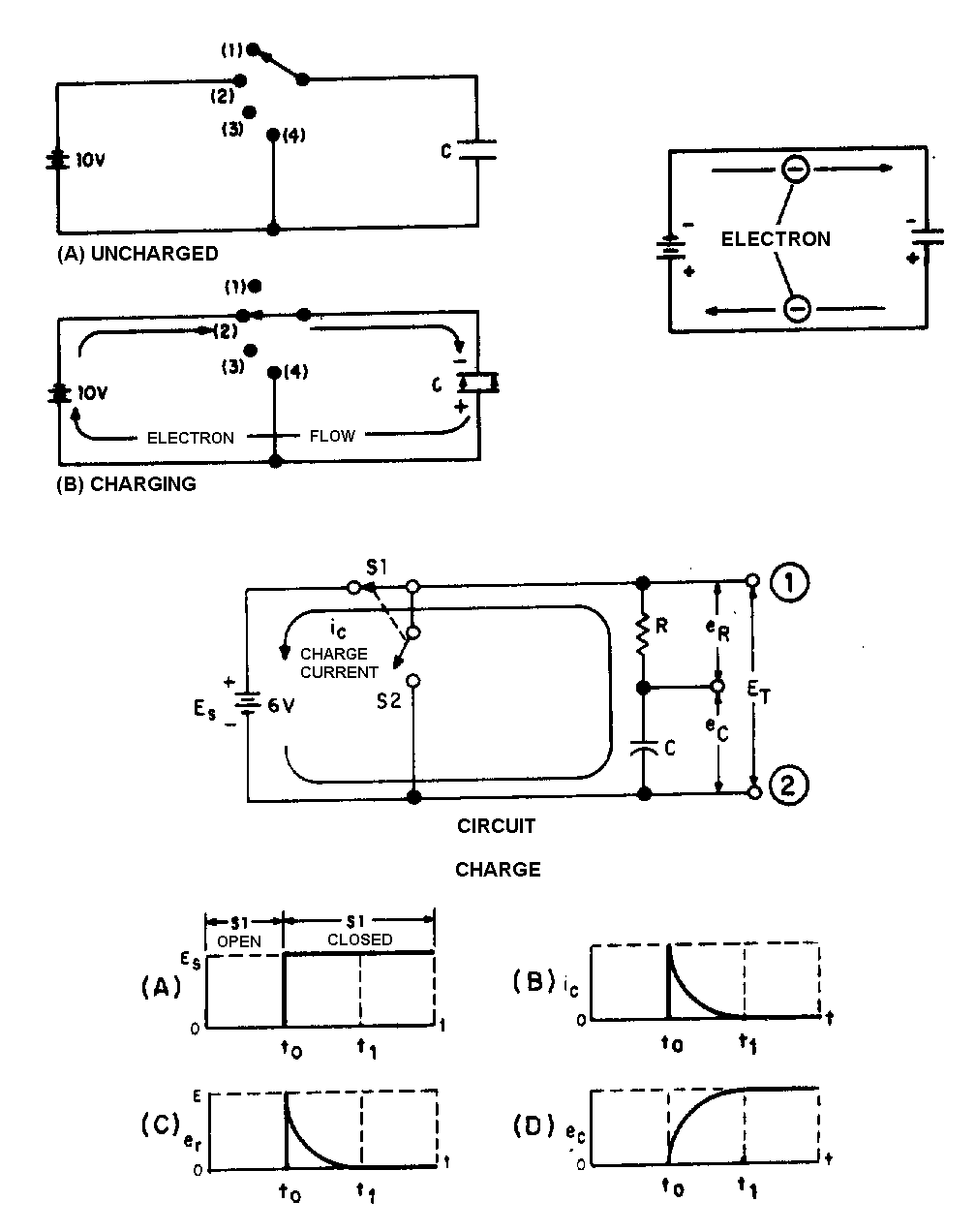
3-36
flows in the circuit. Current will continue to flow until the charges on the two plates become equal. At this point, current ceases to flow. With a dc voltage source, current will flow in the circuit only long enough to charge (or discharge) the capacitor. Thus, a capacitor does NOT allow dc current to flow continuously in a circuit.
FACTORS AFFECTING CAPACITANCE—There are three factors affecting capacitance. One factor is the area of the plate surfaces. Increasing the area of the plate increases the capacitance. Another

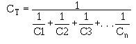
3-37
factor is the amount of space between the plates. The closer the plates, the greater will be the electrostatic field. A greater electrostatic field causes a greater capacitance. The plate spacing is determined by the thickness of the dielectric. The third factor affecting capacitance is the dielectric constant. The value of the dielectric constant is dependent upon the type of dielectric used.
WORKING VOLTAGE—The working voltage of a capacitor is the maximum voltage that can be steadily applied to the capacitor without the capacitor breaking down (shorting). The working voltage depends upon the type of material used as the dielectric (the dielectric constant) and the thickness of the dielectric.
CAPACITOR LOSSES—Power losses in a capacitor are caused by dielectric leakage and dielectric hysteresis. Dielectric leakage loss is caused by the leakage current through the resistance in the dielectric. Although this resistance is extremely high, a small amount of current does flow. Dielectric hysteresis may be defined as an effect in a dielectric material similar to the hysteresis found in a magnetic material.
RC TIME CONSTANT—The time required to charge a capacitor to 63.2 percent of the applied voltage, or to discharge the capacitor to 36.8 percent of its charge. The time constant (t) is equal to the product of the resistance and the capacitance. Expressed as a formula:
where t is in seconds, R is in ohms, and C is in farads.
CAPACITORS IN SERIES—The effect of wiring capacitors in series is to increase the distance between plates. This reduces the total capacitance of the circuit. Total capacitance for series connected capacitors may be computed by the formula:
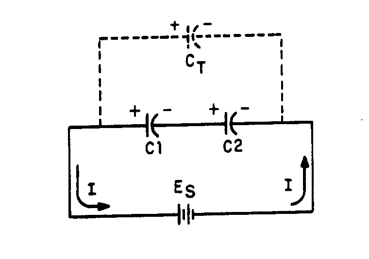
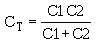
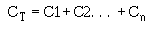
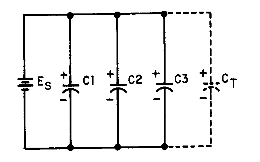
3-38
If an electrical circuit contains only two series connected capacitors, CT may be computed using the following formula:
CAPACITORS IN PARALLEL—The effect of wiring capacitors in parallel is to increase the plate area of the capacitors. Total capacitance (CT) may be found using the formula:
TYPES OF CAPACITORS—Capacitors are manufactured in various forms and may be divided into two main classes-fixed capacitors and variable capacitors. A fixed capacitor is constructed to have a constant or fixed value of capacitance. A variable capacitor allows the capacitance to be varied or adjusted.
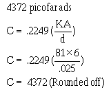
3-39
ANSWERS TO QUESTIONS Q1. THROUGH Q19. A1.
a. A capacitor is a device that stores electrical energy in an electrostatic field. b. Capacitance is the property of a circuit which opposes changes in voltage.
A2.
a. They are polarized from positive to negative. b. They radiate from a charged particle in straight lines and do not form closed loops. c. They have the ability to pass through any known material.
d. They have the ability to distort the orbits of electrons circling the nucleus. A3. Toward the positive charge.
A4. Two pieces of conducting material separated by an insulator. A5. A farad is the unit of capacitance. A capacitor has a capacitance of 1 farad when a difference of 1
volt will charge it with 1 coulomb of electrons. A6.
a. One microfarad equals 10-6 farad. b. One picofarad equals 10-12 farad.
A7.
a. The area of the plates. b. The distance between the plates.
c. The dielectric constant of the material between the plates. A8.
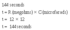
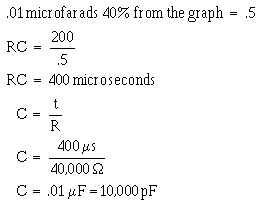
3-40
A9.
a. Hysteresis
b. Dielectric leakage
A10.
a. It is the maximum voltage the capacitor can work without risk of damage. b. 900 volts.
A11.
a. When the capacitor is charging, electrons accumulate on the negative plate and leave the positive plate until the charge on the capacitor is equal to the battery voltage.
b. When the capacitor is discharging, electrons flow from the negatively charged plate to the positively charged plate until the charge on each plate is neutral.
A12. At the instant of the initiation of the action. A13. Zero.
A14.
A15.
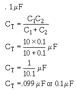
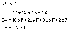

3-41
A16.
A17.
A18.
a. Electrolytic capacitor
b. Trimmer capacitor
A19.
a. ��� �������������pF
b. 630 pF
c. 9600 pF
4-1
CHAPTER 4
INDUCTIVE AND CAPACITIVE REACTANCE
LEARNING OBJECTIVES
Upon completion of this chapter you will be able to:
1. State the effects an inductor has on a change in current and a capacitor has on a change in voltage.
2. State the phase relationships between current and voltage in an inductor and in a capacitor.
3. State the terms for the opposition an inductor and a capacitor offer to ac
4. Write the formulas for inductive and capacitive reactances.
5. State the effects of a change in frequency on X L and XC.
6. State the effects of a change in inductance on X L and a change in capacitance on XC.
7. Write the formula for determining total reactance (X); compute total reactance (X) in a series circuit; and indicate whether the total reactance is capacitive or inductive.
8. State the term given to the total opposition (Z) in an ac circuit.
9. Write the formula for impedance, and calculate the impedance in a series circuit when the values of XC, X L, and R are given.
10. Write the Ohm's law formulas used to determine voltage and current in an ac circuit.
11. Define true power, reactive power, and apparent power; state the unit of measurement for and the formula used to calculate each.
12. State the definition of and write the formula for power factor.
13. Given the power factor and values of X and R in an ac circuit, compute the value of reactance in the circuit, and state the type of reactance that must be connected in the circuit to correct the power factor to unity (1).
14. State the difference between calculating impedance in a series ac circuit and in a parallel ac circuit.
INDUCTIVE AND CAPACITIVE REACTANCE
You have already learned how inductance and capacitance individually behave in a direct current circuit. In this chapter you will be shown how inductance, capacitance, and resistance affect alternating current.
4-2
INDUCTANCE AND ALTERNATING CURRENT
This might be a good place to recall what you learned about phase in chapter 1. When two things are in step, going through a cycle together, falling together and rising together, they are in phase. When they are out of phase, the angle of lead or lag-the number of electrical degrees by which one of the values leads or lags the other-is a measure of the amount they are out of step. The time it takes the current in an inductor to build up to maximum and to fall to zero is important for another reason. It helps illustrate a very useful characteristic of inductive circuits-the current through the inductor always lags the voltage across the inductor.
A circuit having pure resistance (if such a thing were possible) would have the alternating current through it and the voltage across it rising and failing together. This is illustrated in figure 4-1(A), which shows the sine waves for current and voltage in a purely resistive circuit having an ac source. The current and voltage do not have the same amplitude, but they are in phase.
In the case of a circuit having inductance, the opposing force of the counter emf would be enough to keep the current from remaining in phase with the applied voltage. You learned that in a dc circuit containing pure inductance the current took time to rise to maximum even though the full applied voltage was immediately at maximum. Figure 4-1(B) shows the wave forms for a purely inductive ac circuit in steps of quarter-cycles.
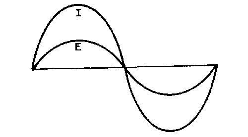
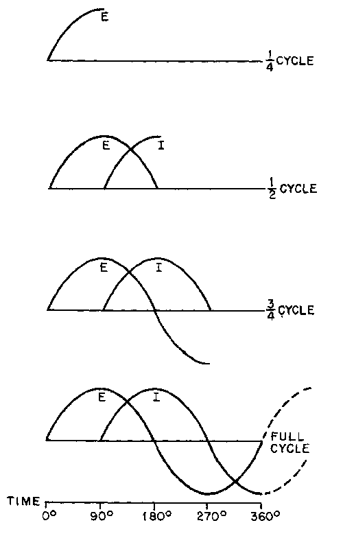
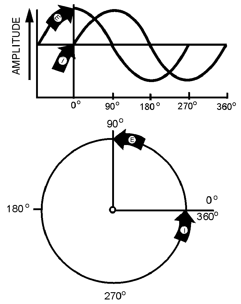
Figure 4-2.—Comparison of sine wave and circle in an inductive circuit.
4-4
With an ac voltage, in the first quarter-cycle (0º to 90º ) the applied ac voltage is continually increasing. If there was no inductance in the circuit, the current would also increase during this first quarter-cycle. You know this circuit does have inductance. Since inductance opposes any change in current flow, no current flows during the first quarter-cycle. In the next quarter-cycle (90º to 180º ) the voltage decreases back to zero; current begins to flow in the circuit and reaches a maximum value at the same instant the voltage reaches zero. The applied voltage now begins to build up to maximum in the other direction, to be followed by the resulting current. When the voltage again reaches its maximum at the end of the third quarter-cycle (270º ) all values are exactly opposite to what they were during the first half-cycle. The applied voltage leads the resulting current by one quarter-cycle or 90 degrees. To complete the full 360º cycle of the voltage, the voltage again decreases to zero and the current builds to a maximum value.
You must not get the idea that any of these values stops cold at a particular instant. Until the applied voltage is removed, both current and voltage are always changing in amplitude and direction.
As you know the sine wave can be compared to a circle. Just as you mark off a circle into 360 degrees, you can mark off the time of one cycle of a sine wave into 360 electrical degrees. This relationship is shown in figure 4-2. By referring to this figure you can see why the current is said to lag the voltage, in a purely inductive circuit, by 90 degrees. Furthermore, by referring to figures 4-2 and 4-1(A) you can see why the current and voltage are said to be in phase in a purely resistive circuit. In a circuit having both resistance and inductance then, as you would expect, the current lags the voltage by an amount somewhere between 0 and 90 degrees.
A simple memory aid to help you remember the relationship of voltage and current in an inductive circuit is the word ELI. Since E is the symbol for voltage, L is the symbol for inductance, and I is the symbol for current; the word ELI demonstrates that current comes after (Lags) voltage in an inductor.
���� ����� ���� ����������� ����� � ��������� �������� ����
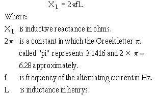
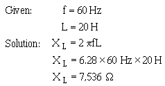
4-5
���� ���������� ����� �� ���� ������� �� ������ �������� ���� ������������� ���
INDUCTIVE REACTANCE
When the current flowing through an inductor continuously reverses itself, as in the case of an ac source, the inertia effect of the cemf is greater than with dc. The greater the amount of inductance (L), the greater the opposition from this inertia effect. Also, the faster the reversal of current, the greater this inertial opposition. This opposing force which an inductor presents to the FLOW of alternating current cannot be called resistance, since it is not the result of friction within a conductor. The name given to it is INDUCTIVE REACTANCE because it is the "reaction" of the inductor to the changing value of alternating current. Inductive reactance is measured in ohms and its symbol is XL.
As you know, the induced voltage in a conductor is proportional to the rate at which magnetic lines of force cut the conductor. The greater the rate (the higher the frequency), the greater the cemf. Also, the induced voltage increases with an increase in inductance; the more ampere-turns, the greater the cemf. Reactance, then, increases with an increase of frequency and with an increase of inductance. The formula for inductive reactance is as follows:
The following example problem illustrates the computation of X L.
���� ���������� �� ��� ���� � �� ���� ����������� ���� � ����� �����
���� ���������� � �������� ��� �� ���� ��� ����� � ������ �� ���� ���
���� ��������� ���� ��� ����� � �� ���� � !� ��"����� �� ���
�#�� ��������� ���� ��� ����� � �� ������������� �� �� �� ���
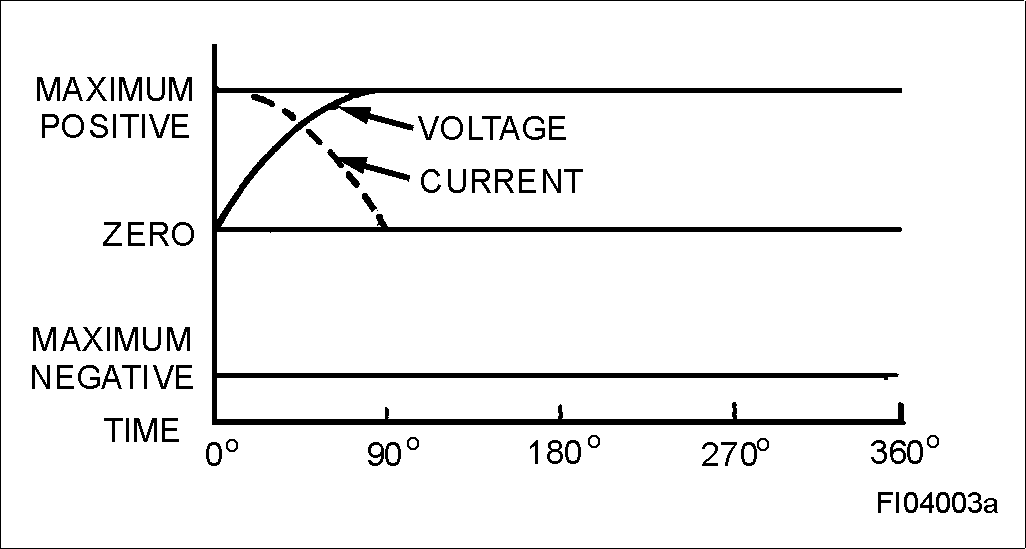
Figure 4-3.—Phase relationship of voltage and current in a capacitive circuit.
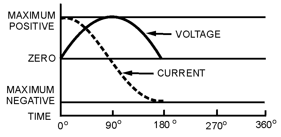
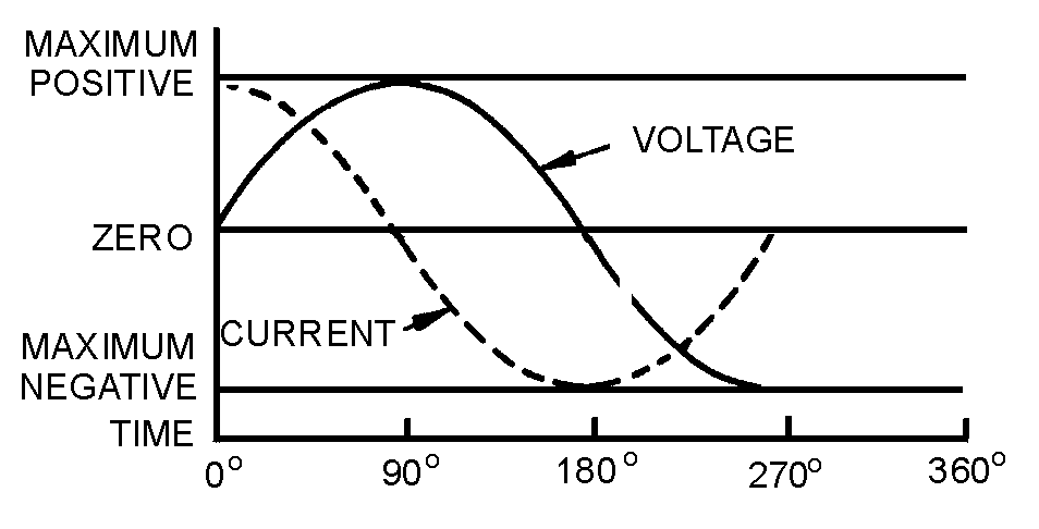
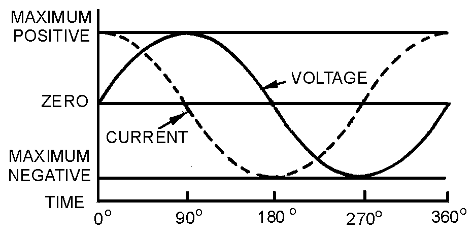
4-6
CAPACITORS AND ALTERNATING CURRENT
The four parts of figure 4-3 show the variation of the alternating voltage and current in a capacitive circuit, for each quarter of one cycle. The solid line represents the voltage across the capacitor, and the dotted line represents the current. The line running through the center is the zero, or reference point, for both the voltage and the current. The bottom line marks off the time of the cycle in terms of electrical degrees. Assume that the ac voltage has been acting on the capacitor for some time before the time represented by the starting point of the sine wave in the figure.
(A)
(B)
( C )
(D)
4-7
At the beginning of the first quarter-cycle (0º to 90º) the voltage has just passed through zero and is increasing in the positive direction. Since the zero point is the steepest part of the sine wave, the voltage is changing at its greatest rate. The charge on a capacitor varies directly with the voltage, and therefore the charge on the capacitor is also changing at its greatest rate at the beginning of the first quarter-cycle. In other words, the greatest number of electrons are moving off one plate and onto the other plate. Thus the capacitor current is at its maximum value, as part (A) of the figure shows.
As the voltage proceeds toward maximum at 90 degrees, its rate of change becomes less and less, hence the current must decrease toward zero. At 90 degrees the voltage across the capacitor is maximum, the capacitor is fully charged, and there is no further movement of electrons from plate to plate. That is why the current at 90 degrees is zero.
At the end of this first quarter-cycle the alternating voltage stops increasing in the positive direction and starts to decrease. It is still a positive voltage, but to the capacitor the decrease in voltage means that the plate which has just accumulated an excess of electrons must lose some electrons. The current flow, therefore, must reverse its direction. Part (B) of the figure shows the current curve to be below the zero line (negative current direction) during the second quarter-cycle (90º to 180º).
At 180 degrees the voltage has dropped to zero. This means that for a brief instant the electrons are equally distributed between the two plates; the current is maximum because the rate of change of voltage is maximum. Just after 180 degrees the voltage has reversed polarity and starts building up its maximum negative peak which is reached at the end of the third quarter-cycle (180º to 270º). During this third quarter-cycle the rate of voltage change gradually decreases as the charge builds to a maximum at 270 degrees. At this point the capacitor is fully charged and it carries the full impressed voltage. Because the capacitor is fully charged there is no further exchange of electrons; therefore, the current flow is zero at this point. The conditions are exactly the same as at the end of the first quarter-cycle (90º) but the polarity is reversed.
Just after 270 degrees the impressed voltage once again starts to decrease, and the capacitor must lose electrons from the negative plate. It must discharge, starting at a minimum rate of flow and rising to a maximum. This discharging action continues through the last quarter-cycle (270º to 360º) until the impressed-voltage has reached zero. At 360 degrees you are back at the beginning of the entire cycle, and everything starts over again.
If you examine the complete voltage and current curves in part D, you will see that the current always arrives at a certain point in the cycle 90 degrees ahead of the voltage, because of the charging and discharging action. You know that this time and place relationship between the current and voltage is called the phase relationship. The voltage-current phase relationship in a capacitive circuit is exactly opposite to that in an inductive circuit. The current of a capacitor leads the voltage across the capacitor by 90 degrees.
You realize that the current and voltage are both going through their individual cycles at the same time during the period the ac voltage is impressed. The current does not go through part of its cycle (charging or discharging), stop, and wait for the voltage to catch up. The amplitude and polarity of the voltage and the amplitude and direction of the current are continually changing. Their positions with respect to each other and to the zero line at any electrical instant-any degree between zero and 360 degrees-can be seen by reading upwards from the time-degree line. The current swing from the positive peak at zero degrees to the negative peak at 180 degrees is NOT a measure of the number of electrons, or the charge on the plates. It is a picture of the direction and strength of the current in relation to the polarity and strength of the voltage appearing across the plates.

4-8
At times it is convenient to use the word "ICE" to recall to mind the phase relationship of the current and voltage in capacitive circuits. I is the symbol for current, and in the word ICE it leads, or comes before, the symbol for voltage, E. C, of course, stands for capacitor. This memory aid is similar to the "ELI" used to remember the current and voltage relationship in an inductor. The phrase "ELI the ICE man" is helpful in remembering the phase relationship in both the inductor and capacitor.
Since the plates of the capacitor are changing polarity at the same rate as the ac voltage, the capacitor seems to pass an alternating current. Actually, the electrons do not pass through the dielectric, but their rushing back and forth from plate to plate causes a current flow in the circuit. It is convenient, however, to say that the alternating current flows "through" the capacitor. You know this is not true, but the expression avoids a lot of trouble when speaking of current flow in a circuit containing a capacitor. By the same short cut, you may say that the capacitor does not pass a direct current (if both plates are connected to a dc source, current will flow only long enough to charge the capacitor). With a capacitor type of hookup in a circuit containing both ac and dc, only the ac will be "passed" on to another circuit.
You have now learned two things to remember about a capacitor: A capacitor will appear to conduct an alternating current and a capacitor will not conduct a direct current.
�$�� ����� ���� ���� �������� ����� � �������������� ���� ��
�%�� ���������� ����� �� ���� ������� �� ������ �������� ���� ������������� ���
CAPACITIVE REACTANCE
So far you have been dealing with the capacitor as a device which passes ac and in which the only opposition to the alternating current has been the normal circuit resistance present in any conductor. However, capacitors themselves offer a very real opposition to current flow. This opposition arises from the fact that, at a given voltage and frequency, the number of electrons which go back and forth from plate to plate is limited by the storage ability-that is, the capacitance-of the capacitor. As the capacitance is increased, a greater number of electrons change plates every cycle, and (since current is a measure of the number of electrons passing a given point in a given time) the current is increased.
Increasing the frequency will also decrease the opposition offered by a capacitor. This occurs because the number of electrons which the capacitor is capable of handling at a given voltage will change plates more often. As a result, more electrons will pass a given point in a given time (greater current flow). The opposition which a capacitor offers to ac is therefore inversely proportional to frequency and to capacitance. This opposition is called CAPACITIVE REACTANCE. You may say that capacitive reactance decreases with increasing frequency or, for a given frequency, the capacitive reactance decreases with increasing capacitance. The symbol for capacitive reactance is XC.
Now you can understand why it is said that the XC varies inversely with the product of the frequency and capacitance. The formula is:
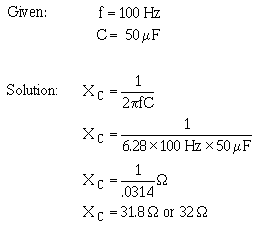
4-9
Where:
XC is capacitive reactance in ohms
f is frequency in Hertz
C is capacitance in farads
π is 6.28 (2 × 3.1416)
The following example problem illustrates the computation of X C.
�&�� ���������� �� ��� ���� � �� ���� ���������������� ���� � ����� �����
��'�� ���������� � �������� ��� �� ���� ������ �� ���� ���
����� ��������� ���� ��� ����� � ��(���� � !� ��"�� �� �� ���
����� ��������� ���� ��� ����� � ��(�������������� ����� �� ���
REACTANCE, IMPEDANCE, AND POWER RELATIONSHIPS IN AC CIRCUITS
Up to this point inductance and capacitance have been explained individually in ac circuits. The rest of this chapter will concern the combination of inductance, capacitance, and resistance in ac circuits.
To explain the various properties that exist within ac circuits, the series RLC circuit will be used. Figure 4-4 is the schematic diagram of the series RLC circuit. The symbol shown in figure 4-4 that is marked E is the general symbol used to indicate an ac voltage source.
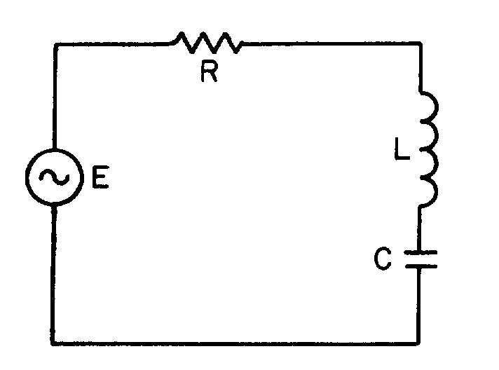
Figure 4-4.—Series RLC circuit.
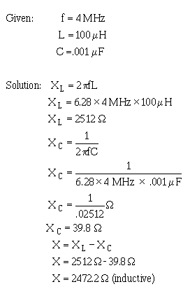
4-10
REACTANCE
The effect of inductive reactance is to cause the current to lag the voltage, while that of capacitive reactance is to cause the current to lead the voltage. Therefore, since inductive reactance and capacitive reactance are exactly opposite in their effects, what will be the result when the two are combined? It is not hard to see that the net effect is a tendency to cancel each other, with the combined effect then equal to the difference between their values. This resultant is called REACTANCE; it is represented by the symbol X; and expressed by the equation X = XL − XC or X = XC − X L. Thus, if a circuit contains 50 ohms of inductive reactance and 25 ohms of capacitive reactance in series, the net reactance, or X, is 50 ohms − 25 ohms, or 25 ohms of inductive reactance.
For a practical example, suppose you have a circuit containing an inductor of 100 µH in series with a capacitor of .001 µF, and operating at a frequency of 4 MHz. What is the value of net reactance, or X?
Now assume you have a circuit containing a 100 - µH inductor in series with a .0002-µF capacitor, and operating at a frequency of 1 MHz. What is the value of the resultant reactance in this case?
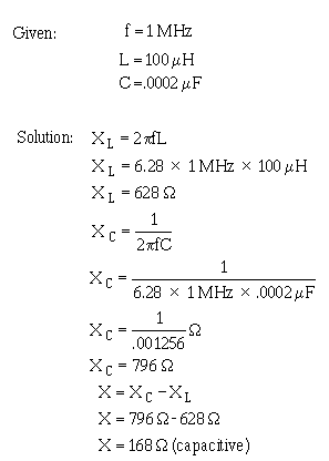
4-11
You will notice that in this case the inductive reactance is smaller than the capacitive reactance and is therefore subtracted from the capacitive reactance.
These two examples serve to illustrate an important point: when capacitive and inductive reactance are combined in series, the smaller is always subtracted from the larger and the resultant reactance always takes the characteristics of the larger.
����� ���������� � ������ ��� � ��������� ����� ������ ������� �� ������������ � ��� ����� �� ��(������ �� ��� �)� ����
����� ���������� �� ������ ���� �� ������ �*�+������� �� ����������������� ����������� � ��'� �������� �����(� ��'� �����*,������ ��� �� ���������������� � ���������� +�
IMPEDANCE
From your study of inductance and capacitance you know how inductive reactance and capacitive reactance act to oppose the flow of current in an ac circuit. However, there is another factor, the resistance, which also opposes the flow of the current. Since in practice ac circuits containing reactance also contain resistance, the two combine to oppose the flow of current. This combined opposition by the resistance and the reactance is called the IMPEDANCE, and is represented by the symbol Z.
Since the values of resistance and reactance are both given in ohms, it might at first seem possible to determine the value of the impedance by simply adding them together. It cannot be done so easily, however. You know that in an ac circuit which contains only resistance, the current and the voltage will be in step (that is, in phase), and will reach their maximum values at the same instant. You also know that in an ac circuit containing only reactance the current will either lead or lag the voltage by one-quarter of a cycle or 90 degrees. Therefore, the voltage in a purely reactive circuit will differ in phase by 90 degrees from that in a purely resistive circuit and for this reason reactance and resistance are rot combined by simply adding them.
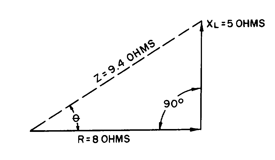
Figure 4-5.—Vector diagram showing relationship of resistance, inductive reactance, and impedance in a series circuit.
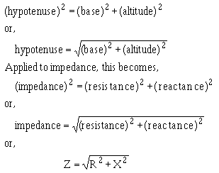
4-12
When reactance and resistance are combined, the value of the impedance will be greater than either. It is also true that the current will not be in step with the voltage nor will it differ in phase by exactly 90 degrees from the voltage, but it will be somewhere between the in-step and the 90-degree out-of-step conditions. The larger the reactance compared with the resistance, the more nearly the phase difference will approach 90º . The larger the resistance compared to the reactance, the more nearly the phase difference will approach zero degrees.
If the value of resistance and reactance cannot simply be added together to find the impedance, or Z, how is it determined? Because the current through a resistor is in step with the voltage across it and the current in a reactance differs by 90 degrees from the voltage across it, the two are at right angles to each other. They can therefore be combined by means of the same method used in the construction of a right- angle triangle.
Assume you want to find the impedance of a series combination of 8 ohms resistance and 5 ohms inductive reactance. Start by drawing a horizontal line, R, representing 8 ohms resistance, as the base of the triangle. Then, since the effect of the reactance is always at right angles, or 90 degrees, to that of the resistance, draw the line XL, representing 5 ohms inductive reactance, as the altitude of the triangle. This is shown in figure 4-5. Now, complete the hypotenuse (longest side) of the triangle. Then, the hypotenuse represents the impedance of the circuit.
One of the properties of a right triangle is:
Now suppose you apply this equation to check your results in the example given above.
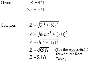
Figure 4-6.—Vector diagram showing relationship of resistance, capacitive reactance, and impedance in a series circuit.
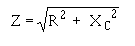
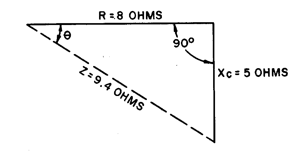
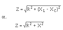
4-13
When you have a capacitive reactance to deal with instead of inductive reactance as in the previous example, it is customary to draw the line representing the capacitive reactance in a downward direction. This is shown in figure 4-6. The line is drawn downward for capacitive reactance to indicate that it acts in a direction opposite to inductive reactance which is drawn upward. In a series circuit containing capacitive reactance the equation for finding the impedance becomes:
In many series circuits you will find resistance combined with both inductive reactance and capacitive reactance. Since you know that the value of the reactance, X, is equal to the difference between the values of the inductive reactance, XL, and the capacitive reactance, XC, the equation for the impedance in a series circuit containing R, XL, and XC then becomes:
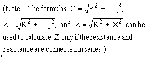
Figure 4-7.—Vector diagram showing relationship of resistance, reactance (capacitive and inductive), and impedance in a series circuit.
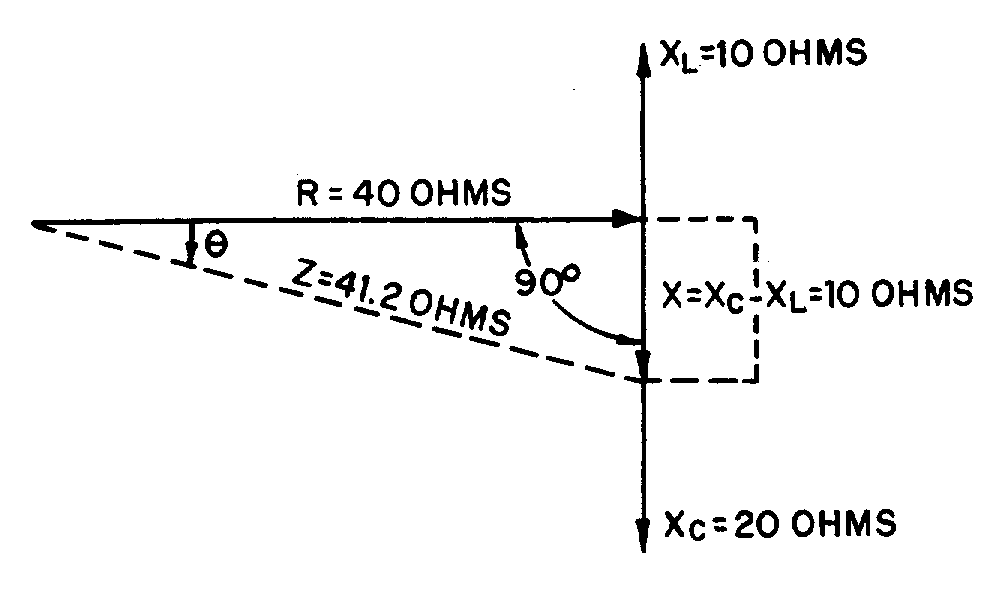
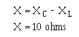
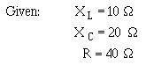
4-14
In figure 4-7 you will see the method which may be used to determine the impedance in a series circuit consisting of resistance, inductance, and capacitance.
Assume that 10 ohms inductive reactance and 20 ohms capacitive reactance are connected in series with 40 ohms resistance. Let the horizontal line represent the resistance R. The line drawn upward from the end of R, represents the inductive reactance, XL. Represent the capacitive reactance by a line drawn downward at right angles from the same end of R. The resultant of XL and XC is found by subtracting XL from XC. This resultant represents the value of X.
Thus:
The line, Z, will then represent the resultant of R and X. The value of Z can be calculated as follows:
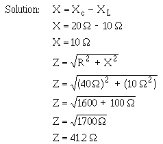
Figure 4-8.—Series LC circuit.

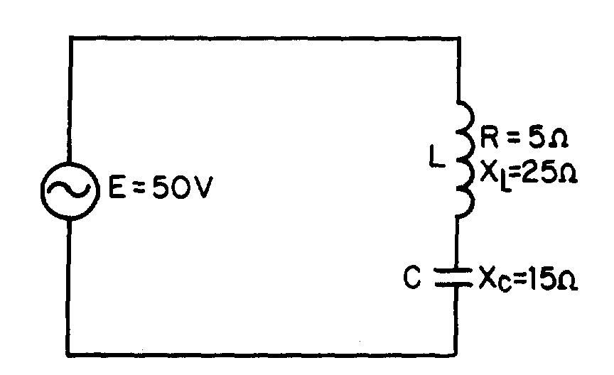
4-15
����� ������ ��������� ��� �� ���� �� ���� ��� ������������������
��#�� ����� ����������� ��� ��������� ��� ��� ���� ������ �� ���� �������� �� �����������
��$�� ���������� ����� � �-������� �� ��������������� � �� �.�#� ���/��(�.��� ���/�����0�.��� �����
OHMS LAW FOR AC
In general, Ohm's law cannot be applied to alternating-current circuits since it does not consider the reactance which is always present in such circuits. However, by a modification of Ohm's law which does take into consideration the effect of reactance we obtain a general law which is applicable to ac circuits. Because the impedance, Z, represents the combined opposition of all the reactances and resistances, this general law for ac is,
this general modification applies to alternating current flowing in any circuit, and any one of the values may be found from the equation if the others are known.
For example, suppose a series circuit contains an inductor having 5 ohms resistance and 25 ohms inductive reactance in series with a capacitor having 15 ohms capacitive reactance. If the voltage is 50 volts, what is the current? This circuit can be drawn as shown in figure 4-8.
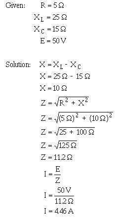
4-16
Now suppose the circuit contains an inductor having 5 ohms resistance and 15 ohms inductive reactance in series with a capacitor having 10 ohms capacitive reactance. If the current is 5 amperes, what is the voltage?
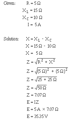
4-17
��%�� ������� ��� �1��2������ ��������� �������������������� �� � ���� �� ���� ��������� ����
POWER IN AC CIRCUITS
You know that in a direct current circuit the power is equal to the voltage times the current, or P = E × I. If a voltage of 100 volts applied to a circuit produces a current of 10 amperes, the power is 1000 watts. This is also true in an ac circuit when the current and voltage are in phase; that is, when the circuit is effectively resistive. But, if the ac circuit contains reactance, the current will lead or lag the voltage by a certain amount (the phase angle). When the current is out of phase with the voltage, the power indicated by the product of the applied voltage and the total current gives only what is known as the APPARENT POWER. The TRUE POWER depends upon the phase angle between the current and voltage. The symbol for phase angle is ��(Theta).
When an alternating voltage is impressed across a capacitor, power is taken from the source and stored in the capacitor as the voltage increases from zero to its maximum value. Then, as the impressed voltage decreases from its maximum value to zero, the capacitor discharges and returns the power to the source. Likewise, as the current through an inductor increases from its zero value to its maximum value the field around the inductor builds up to a maximum, and when the current decreases from maximum to zero the field collapses and returns the power to the source. You can see therefore that no power is used up in either case, since the power alternately flows to and from the source. This power that is returned to the source by the reactive components in the circuit is called REACTIVE POWER.
In a purely resistive circuit all of the power is consumed and none is returned to the source; in a purely reactive circuit no power is consumed and all of the power is returned to the source. It follows that in a circuit which contains both resistance and reactance there must be some power dissipated in the resistance as well as some returned to the source by the reactance. In figure 4-9 you can see the relationship between the voltage, the current, and the power in such a circuit. The part of the power curve which is shown below the horizontal reference line is the result of multiplying a positive instantaneous
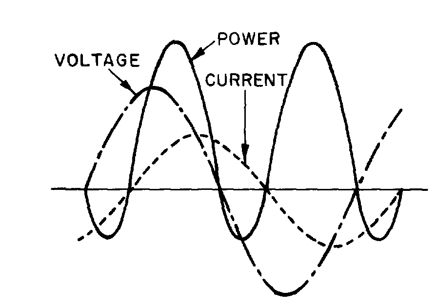
Figure 4-9.—Instantaneous power when current and voltage are out of phase.
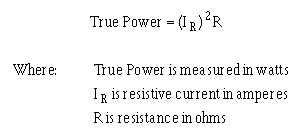
4-18
value of current by a negative instantaneous value of the voltage, or vice versa. As you know, the product obtained by multiplying a positive value by a negative value will be negative. Therefore the power at that instant must be considered as negative power. In other words, during this time the reactance was returning power to the source.
The instantaneous power in the circuit is equal to the product of the applied voltage and current through the circuit. When the voltage and current are of the same polarity they are acting together and taking power from the source. When the polarities are unlike they are acting in opposition and power is being returned to the source. Briefly then, in an ac circuit which contains reactance as well as resistance, the apparent power is reduced by the power returned to the source, so that in such a circuit the net power, or true power, is always less than the apparent power.
Calculating True Power in AC Circuits
As mentioned before, the true power of a circuit is the power actually used in the circuit. This power, measured in watts, is the power associated with the total resistance in the circuit. To calculate true power, the voltage and current associated with the resistance must be used. Since the voltage drop across the resistance is equal to the resistance multiplied by the current through the resistance, true power can be calculated by the formula:
For example, find the true power of the circuit shown in figure 4-10.
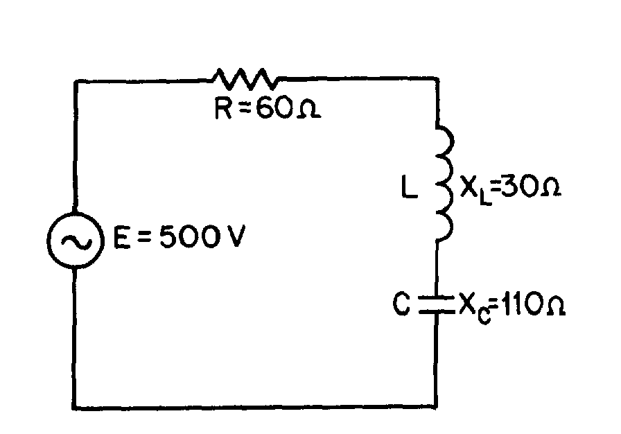
Figure 4-10.—Example circuit for determining power.
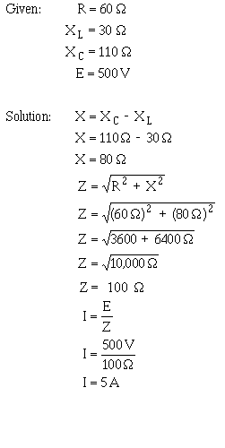
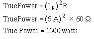
4-19
Since the current in a series circuit is the same in all parts of the circuit:
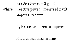
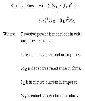
4-20
��&�� ���������� ���� �� � ��������������������
��'�� ���������� ������ �� ���� � ��� ���� �� � ���
����� ���������� � ������ ����������������� �� � ���
Calculating Reactive Power in AC Circuits
The reactive power is the power returned to the source by the reactive components of the circuit. This type of power is measured in Volt-Amperes-Reactive, abbreviated var.
Reactive power is calculated by using the voltage and current associated with the circuit reactance.
Since the voltage of the reactance is equal to the reactance multiplied by the reactive current, reactive power can be calculated by the formula:
Another way to calculate reactive power is to calculate the inductive power and capacitive power and subtract the smaller from the larger.
Either one of these formulas will work. The formula you use depends upon the values you are given in a circuit.
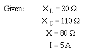
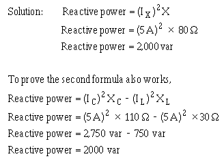
4-21
For example, find the reactive power of the circuit shown in figure 4-10.
Since this is a series circuit, current (I) is the same in all parts of the circuit.
����� ���������� �� ����� �� � ��������������������
����� ���������� ������ �� ���� � ��� ��� ����� �� � ���
����� ���������� � ������ ��� ��������� ����� �� � ���
Calculating Apparent Power in AC Circuits.
Apparent power is the power that appears to the source because of the circuit impedance. Since the impedance is the total opposition to ac, the apparent power is that power the voltage source "sees." Apparent power is the combination of true power and reactive power. Apparent power is not found by simply adding true power and reactive power just as impedance is not found by adding resistance and reactance.
To calculate apparent power, you may use either of the following formulas:
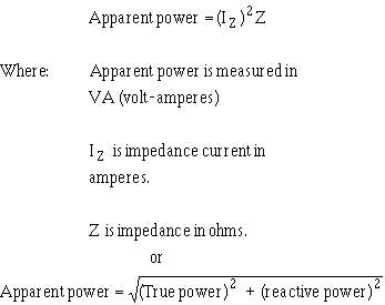
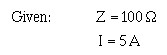
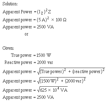
4-22
For example, find the apparent power for the circuit shown in figure 4-10.
Recall that current in a series circuit is the same in all parts of the circuit.
����� ������������� ���� � ���
��#�� ���������� ������ �� ���� � ��� ������� ���� � ���
��$�� ���������� � ������ ������� ���� � ���
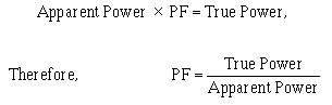
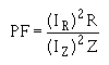

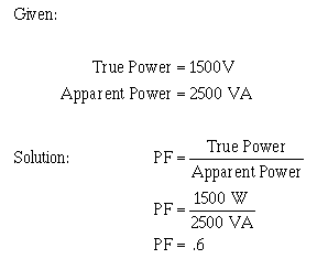
4-23
Power Factor
The POWER FACTOR is a number (represented as a decimal or a percentage) that represents the portion of the apparent power dissipated in a circuit.
If you are familiar with trigonometry, the easiest way to find the power factor is to find the cosine of the phase angle (�). The cosine of the phase angle is equal to the power factor.
You do not need to use trigonometry to find the power factor. Since the power dissipated in a circuit is true power, then:
If true power and apparent power are known you can use the formula shown above.
Going one step further, another formula for power factor can be developed. By substituting the equations for true power and apparent power in the formula for power factor, you get:
Since current in a series circuit is the same in all parts of the circuit, IR equals IZ. Therefore, in a series circuit,
For example, to compute the power factor for the series circuit shown in figure 4-10, any of the above methods may be used.
Another method:
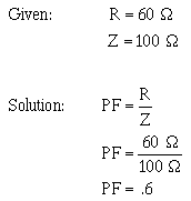
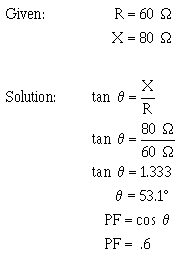
4-24
If you are familiar with trigonometry you can use it to solve for angle � and the power factor by referring to the tables in appendices V and VI.
NOTE: As stated earlier the power factor can be expressed as a decimal or percentage. In this example the decimal number .6 could also be expressed as 60%.
��%�� ���������� �� � �� ��� �� ������������
��&�� ����������� � ���� �������� ��� ��������� ��� �� � �� ��� �� ������������
Power Factor Correction
The apparent power in an ac circuit has been described as the power the source "sees". As far as the source is concerned the apparent power is the power that must be provided to the circuit. You also know that the true power is the power actually used in the circuit. The difference between apparent power and true power is wasted because, in reality, only true power is consumed. The ideal situation would be for apparent power and true power to be equal. If this were the case the power factor would be 1 (unity) or 100 percent. There are two ways in which this condition can exist. (1) If the circuit is purely resistive or (2) if the circuit "appears" purely resistive to the source. To make the circuit appear purely resistive there must be no reactance. To have no reactance in the circuit, the inductive reactance (XL) and capacitive reactance (X C) must be equal.
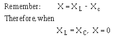
4-25
The expression "correcting the power factor" refers to reducing the reactance in a circuit.
The ideal situation is to have no reactance in the circuit. This is accomplished by adding capacitive reactance to a circuit which is inductive and inductive reactance to a circuit which is capacitive. For example, the circuit shown in figure 4-10 has a total reactance of 80 ohms capacitive and the power factor was .6 or 60 percent. If 80 ohms of inductive reactance were added to this circuit (by adding another inductor) the circuit would have a total reactance of zero ohms and a power factor of 1 or 100 percent. The apparent and true power of this circuit would then be equal.
��'�� 3�������������������� ����� ������ � ��'� ������������ �������� ����� ������� � ��'� �����4� � � � �� ��� ������%&�������� ����� �� � ����"�� �� �� ����� �� � �� ��� ��� �����"��
SERIES RLC CIRCUITS
The principles and formulas that have been presented in this chapter are used in all ac circuits. The examples given have been series circuits.
This section of the chapter will not present any new material, but will be an example of using all the principles presented so far. You should follow each example problem step by step to see how each formula used depends upon the information determined in earlier steps. When an example calls for solving for square root, you can practice using the square-root table by looking up the values given.
The example series RLC circuit shown in figure 4-11 will be used to solve for XL, XC, X, Z, IT, true power, reactive power, apparent power, and power factor.
The values solved for will be rounded off to the nearest whole number.
First solve for XL and XC.
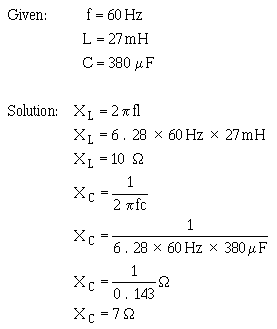
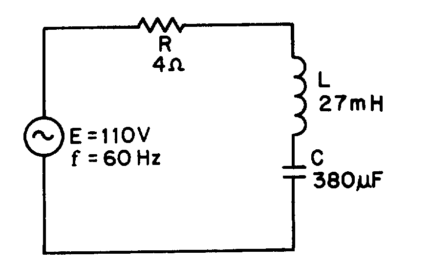
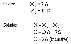
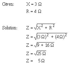
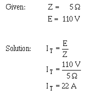
4-27
Use the value of X to solve for Z.
This value of Z can be used to solve for total current (IT).
Since current is equal in all parts of a series circuit, the value of IT can be used to solve for the various values of power.
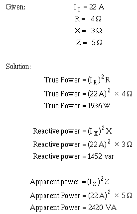
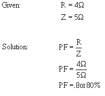
4-28
The power factor can now be found using either apparent power and true power or resistance and impedance. The mathematics in this example is easier if you use impedance and resistance.
PARALLEL RLC CIRCUITS
When dealing with a parallel ac circuit, you will find that the concepts presented in this chapter for series ac circuits still apply. There is one major difference between a series circuit and a parallel circuit that must be considered. The difference is that current is the same in all parts of a series circuit, whereas voltage is the same across all branches of a parallel circuit. Because of this difference, the total impedance of a parallel circuit must be computed on the basis of the current in the circuit.
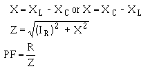
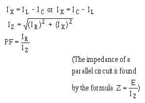
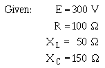
4-29
You should remember that in the series RLC circuit the following three formulas were used to find reactance, impedance, and power factor:
When working with a parallel circuit you must use the following formulas instead:
NOTE: If no value for E is given in a circuit, any value of E can be assumed to find the values of IL, IC, IX, IR, and IZ. The same value of voltage is then used to find impedance.
For example, find the value of Z in the circuit shown in figure 4-12.
The first step in solving for Z is to calculate the individual branch currents.
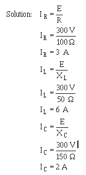
Figure 4-12.—Parallel RLC circuit.
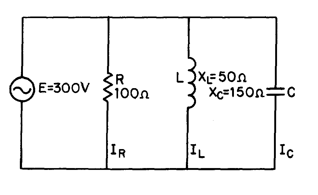
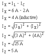
4-30
Using the values for IR, IL, and IC, solve for IX and I Z.
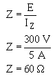
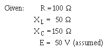
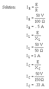
4-31
Using this value of IZ, solve for Z.
If the value for E were not given and you were asked to solve for Z, any value of E could be assumed. If, in the example problem above, you assume a value of 50 volts for E, the solution would be:
First solve for the values of current in the same manner as before.
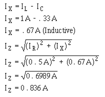
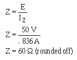
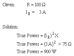
4-32
Solve for IX and IZ.
Solve for Z.
When the voltage is given, you can use the values of currents, I R, IX, and IZ, to calculate for the true power, reactive power, apparent power, and power factor. For the circuit shown in figure 4-12, the calculations would be as follows.
To find true power,
To find reactive power, first find the value of reactance (X).
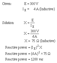
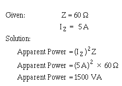
4-33
To find apparent power,
The power factor in a parallel circuit is found by either of the following methods.
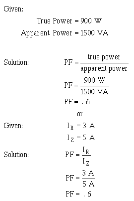
4-34
����� ���������� ��� � �� �� �� ����������������� ���� ������� �� ���������������������������� ����� ���������
SUMMARY
With the completion of this chapter you now have all the building blocks for electrical circuits. The subjects covered from this point on will be based upon the concepts and relationships that you have learned. The following summary is a brief review of the subjects covered in this chapter.
INDUCTANCE IN AC CIRCUITS—An inductor in an ac circuit opposes any change in current flow just as it does in a dc circuit.
PHASE RELATIONSHIPS OF AN INDUCTOR—The current lags the voltage by 90º in an inductor (ELI).
INDUCTIVE REACTANCE—The opposition an inductor offers to ac is called inductive reactance. It will increase if there is an increase in frequency or an increase in inductance. The symbol is XL, and the formula is XL = 2πfL.
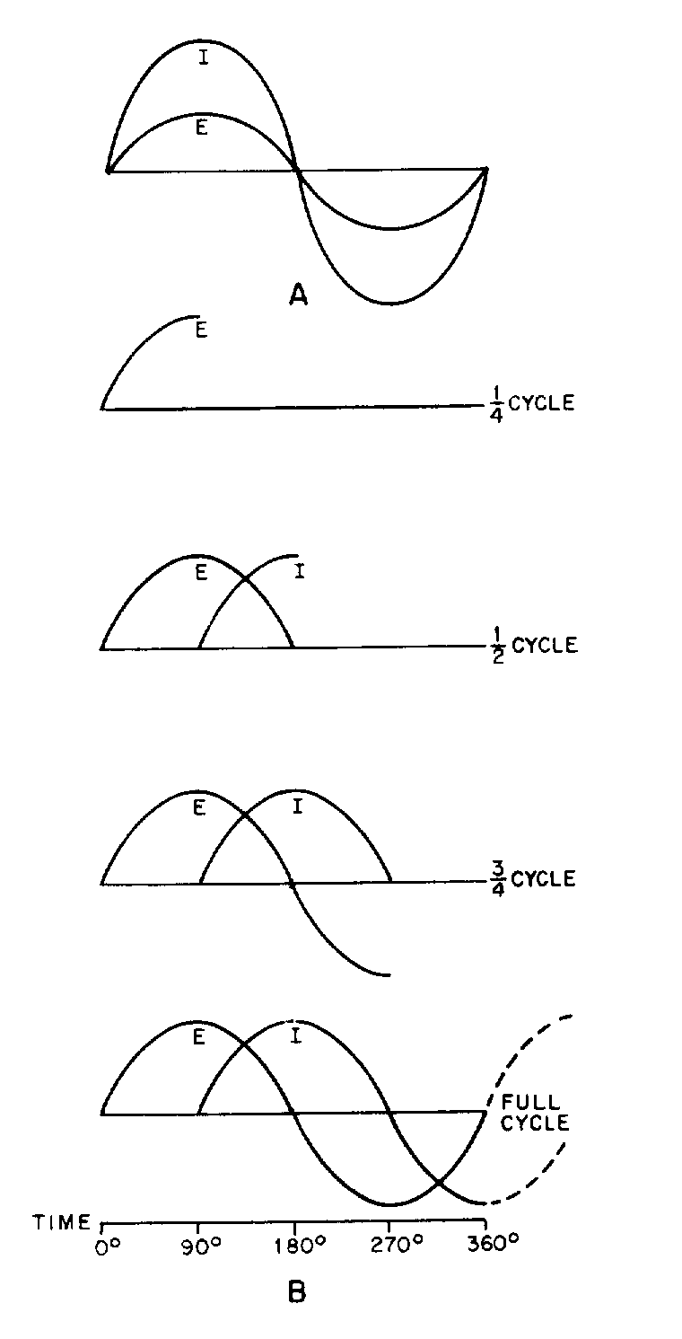
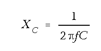
4-35
CAPACITANCE IN AC CIRCUITS—A capacitor in an ac circuit opposes any change in voltage just as it does in a dc circuit.
PHASE RELATIONSHIPS OF A CAPACITOR—The current leads the voltage by 90º in a capacitor (ICE).
CAPACITIVE REACTANCE—The opposition a capacitor offers to ac is called capacitive reactance. Capacitive reactance will decrease if there is an increase in frequency or an increase in capacitance. The symbol is XC and the formula is
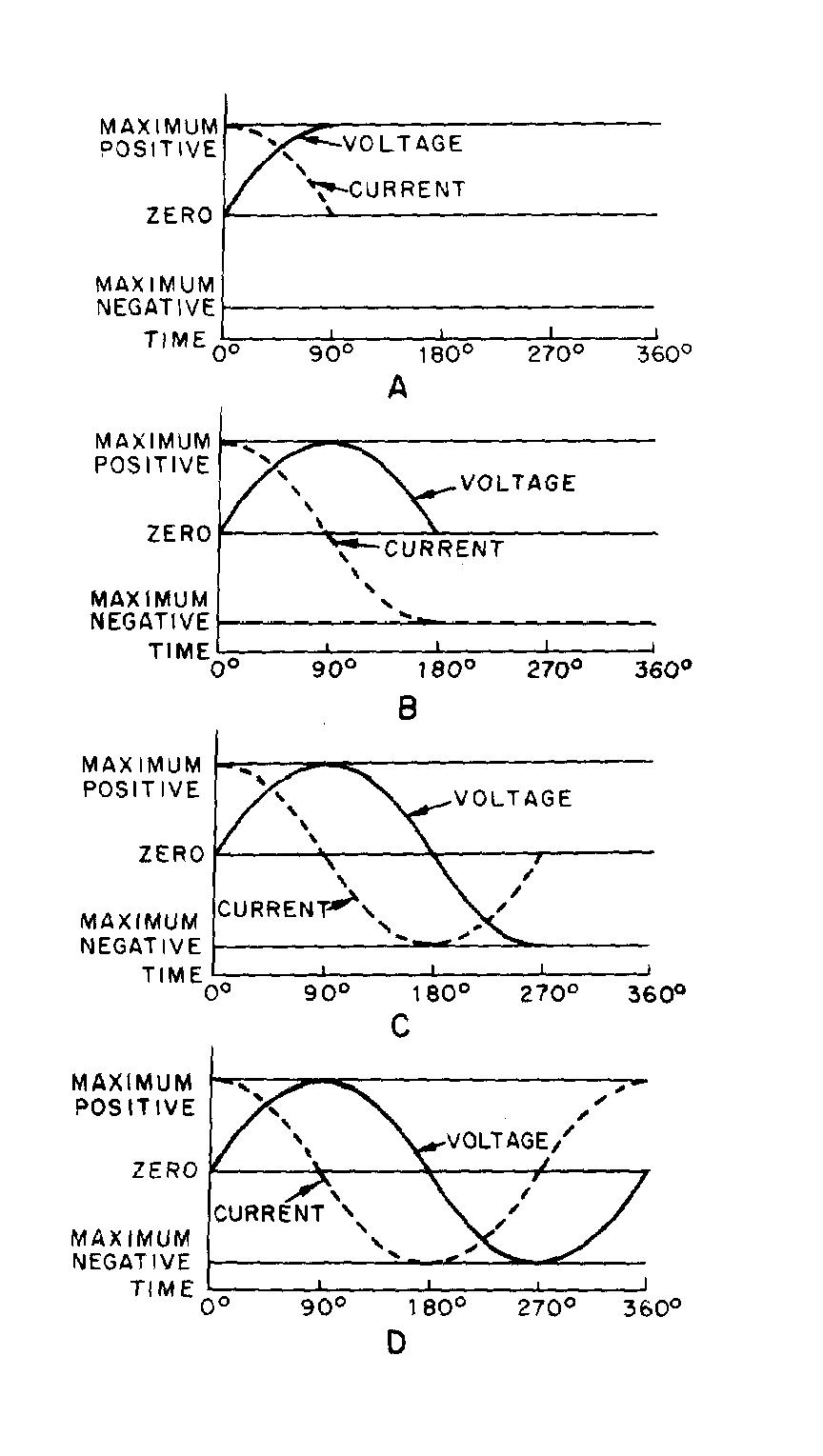
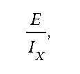
4-36
TOTAL REACTANCE—The total reactance of a series ac circuit is determined by the formula X = XL − XC or X = XC − X L. The total reactance in a series circuit is either capacitive or inductive depending upon the largest value of XC and XL. In a parallel circuit the reactance is determined by
where IX = IC − I L or IX = IL − IC. The reactance in a parallel circuit is either capacitive or inductive depending upon the largest value of IL and IC.
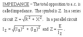
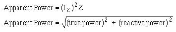
4-37
PHASE ANGLE—The number of degrees that current leads or lags voltage in an ac circuit is called the phase angle. The symbol is �.
OHM'S LAW FORMULAS FOR AC—The formulas derived for Ohm's law used in ac are: E = IZ and I = E/Z.
TRUE POWER—The power dissipated across the resistance in an ac circuit is called true power. It is measured in watts and the formula is: True Power = (IR)
2R.
REACTIVE POWER—The power returned to the source by the reactive elements of the circuit is called reactive power. It is measured in volt-amperes reactive (var). The formula is: Reactive Power = (IX)
2X.
APPARENT POWER—The power that appears to the source because of circuit impedance is called apparent power. It is the combination of true power and reactive power and is measured in volt- amperes (VA). The formulas are:
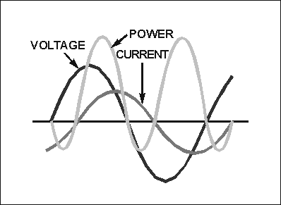
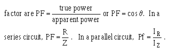
4-38
POWER FACTOR—The portion of the apparent power dissipated in a circuit is called the power factor of the circuit. It can be expressed as a decimal or a percentage. The formulas for power
POWER FACTOR CORRECTION—To reduce losses in a circuit the power factor should be as close to unity or 100% as possible. This is done by adding capacitive reactance to a circuit when the total reactance is inductive. If the total reactance is capacitive, inductive reactance is added in the circuit.
ANSWERS TO QUESTIONS Q1. THROUGH Q31.
3��� 3�������� �� �� � ��������� �������� ����
3��� (��� ��������� ���� ��"�&'5 �*6 ,+��
3��� ,������� �� ������ ��
3��� � �.��π ��
3��� � ����� �� ���
3#�� � �� �� �� ���

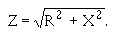

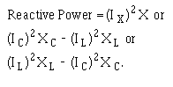
4-39
3$�� 4� �������� �� �� � ����"������ ����� ���� ��
3%�� (��� ���� ����� ���� ��"�&'5 �*,(6+��
3&�� (�������� �� ������ ��
3�'��
3���� �(����� �� ���
3���� �(�� �� �� ���
3���� ��.�� �7��(� ����.���(�7�� �
3���� �'��*��������� +��
3���� ,�� ���� ��
3�#�� �
3�$�� -�.����
3�%�� �
3�&�� 4�� �� � ������� �� � ���������� ������� �� ������� � ��� ��������� ���� �� � ���������"��� ����� �� ����������
3�'�� ������
3���� 4�� �8 � ��.�*,0+ ��0��
3���� 0 ����� �� � ������� �� � ��� ���� ��� ��� �� ��� ��"��� �� ����� �� �� � ���� ��� ����������
3���� �����
3���� �
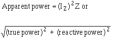
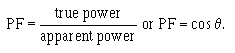
4-40
3���� 4� �� � ���������� ����� ��� �� ��� �� ���� � ������������ ���� /� ���� �� ������� �� ���� � � � ������� ����� �� � ���
3�#�� 93�*� ��7��� � �+��
3�$�� �
3�%�� 8:���������� ��� �� � �������� �� ��� �� ������ ���� � ���������"��������� ����������������
3�&�� �
3�'�� 3����'� ���� ���������� �� ������ �� ��� ����������
3���� ,����� �� ������������� ���� ������������ �� � ���� ����� �� �� ������� ������ ������ ��,���� ������ ���������/��� ����� �� �� ������ ����� �������� ����� ����� ��������� ��� ��� ��������� �� ���� ���� ���*��� ���� ����� ��+�������������� ������� ������ ����� ��� �� ��� �� ���� �� ��������� ��� �
��� ���� ��


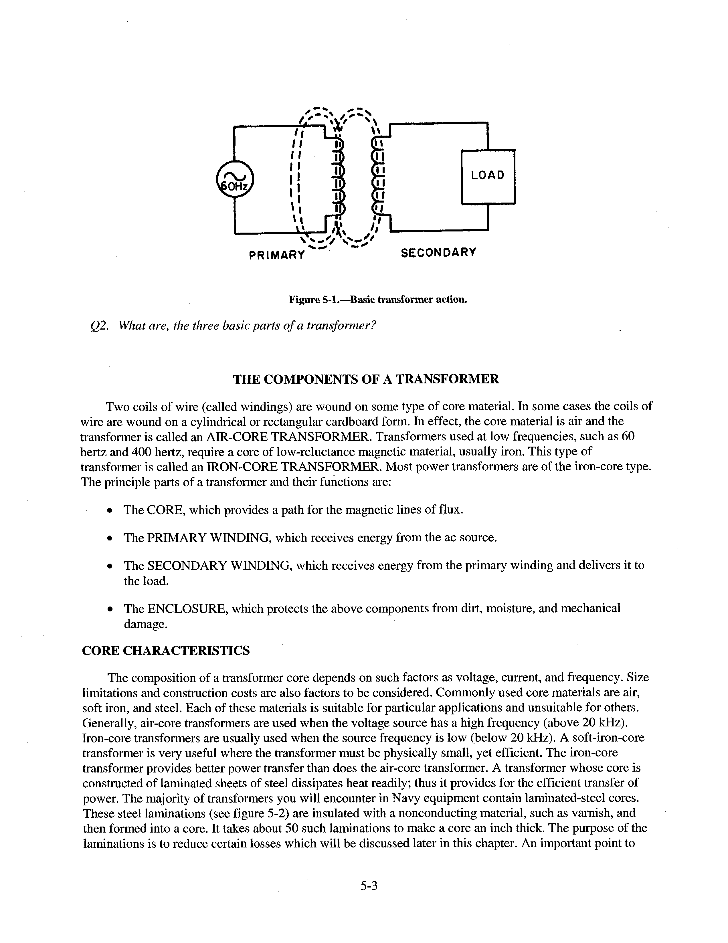


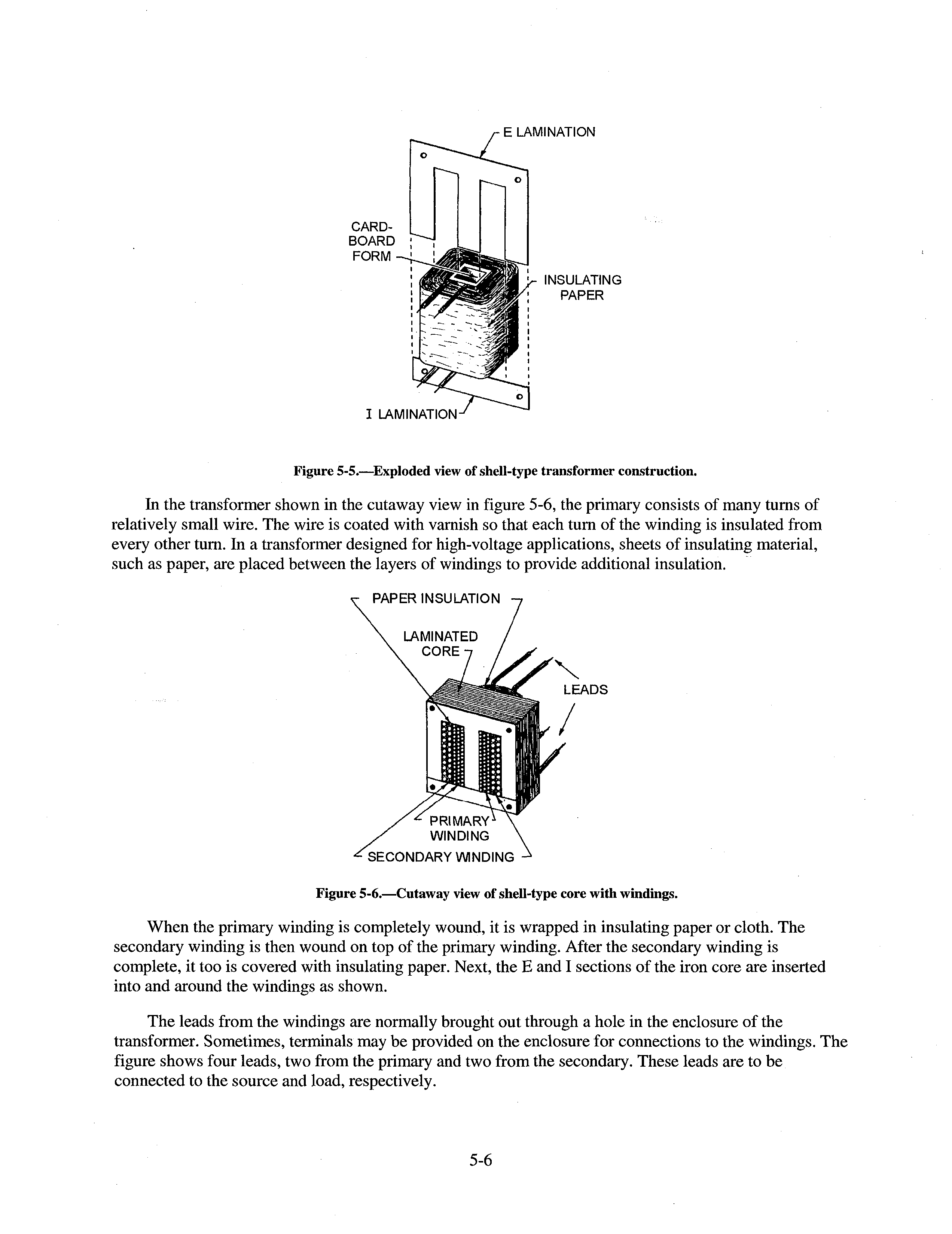
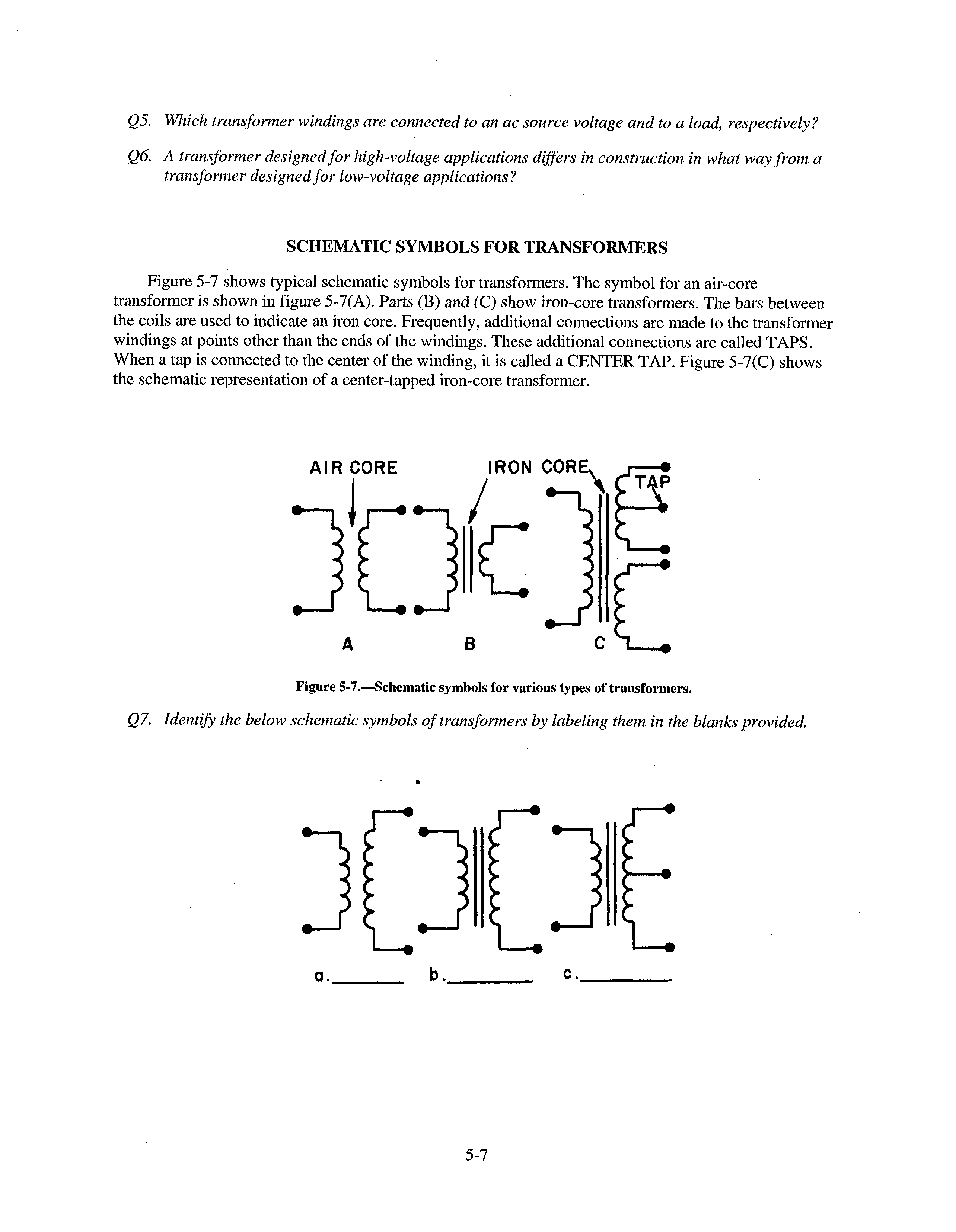
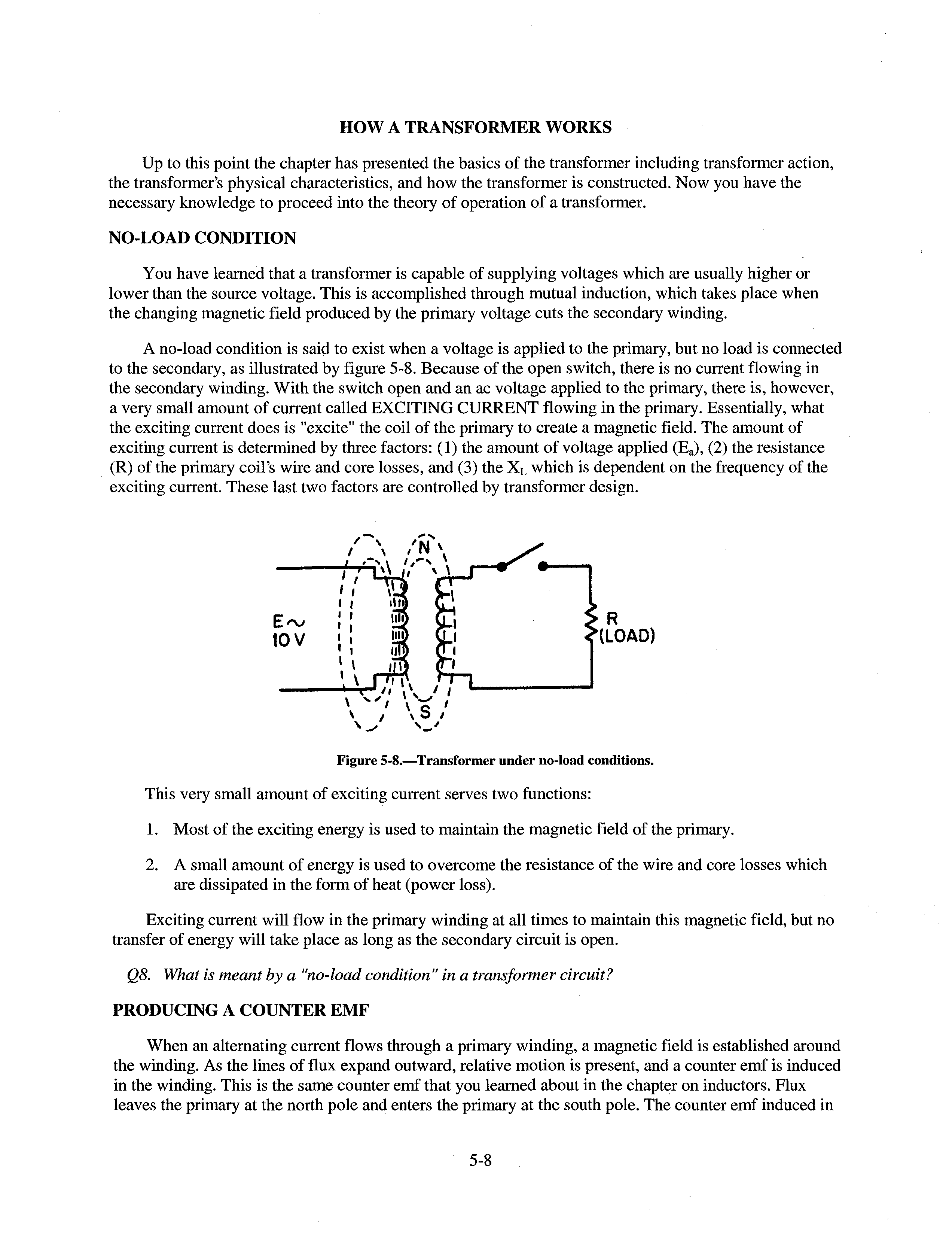
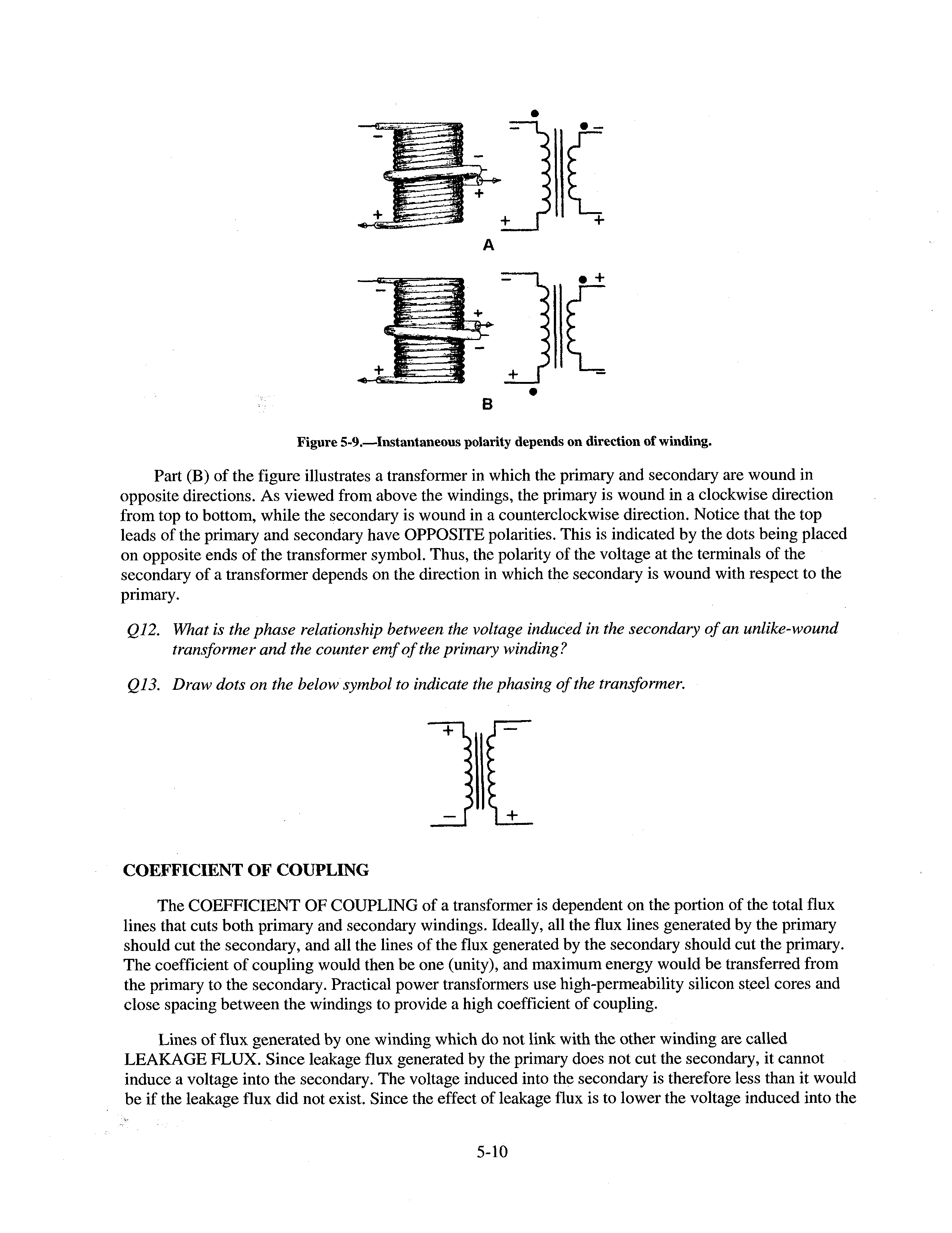


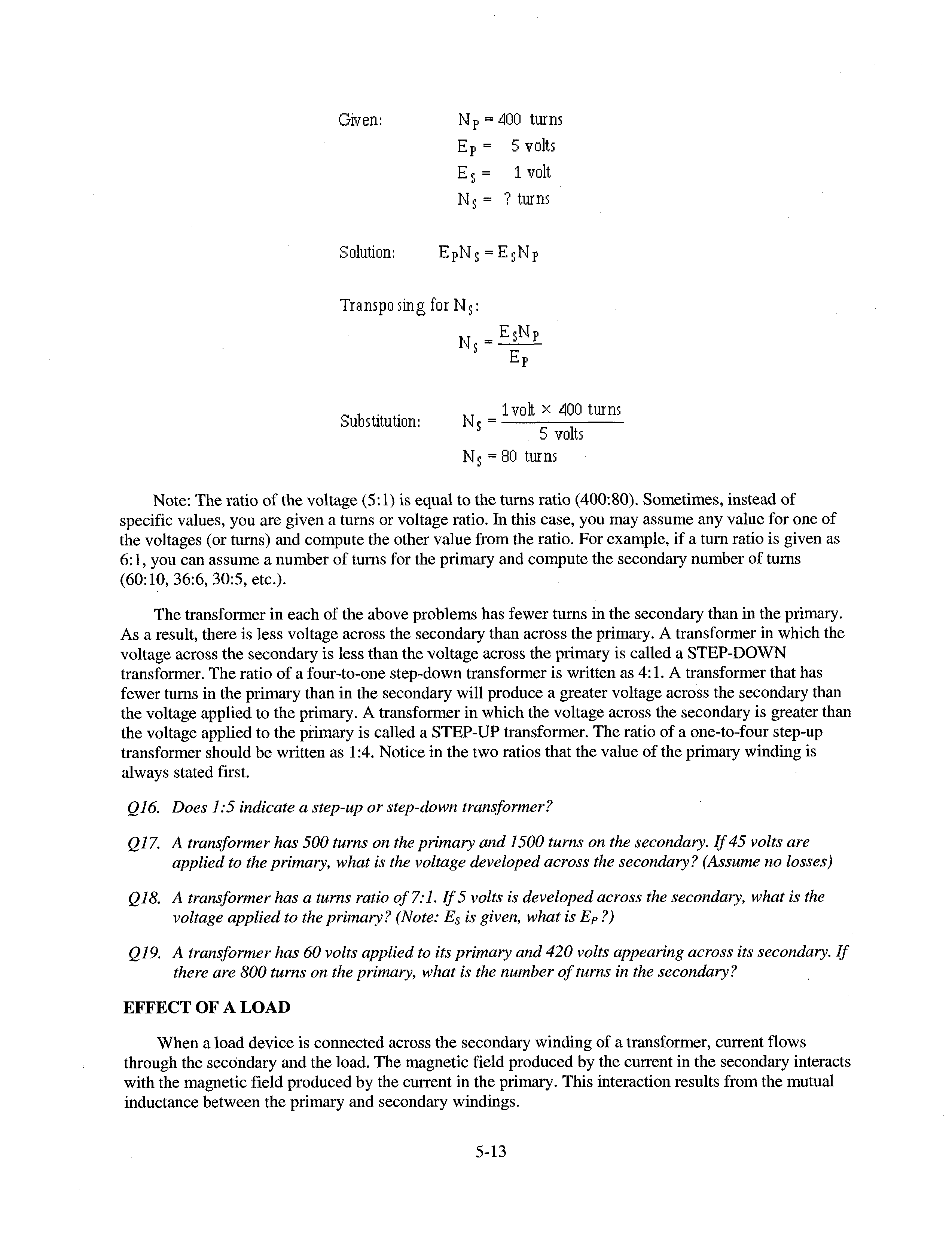


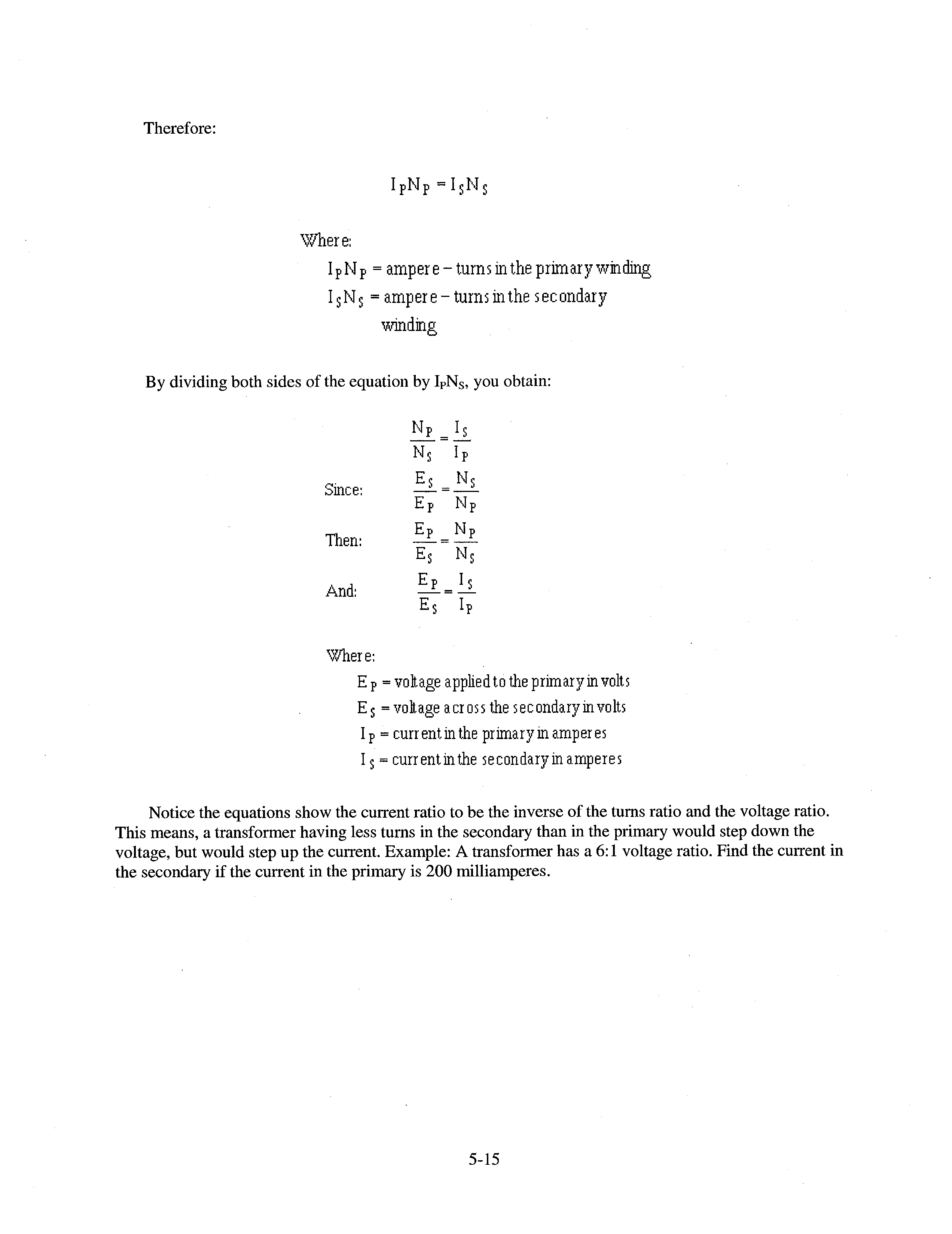
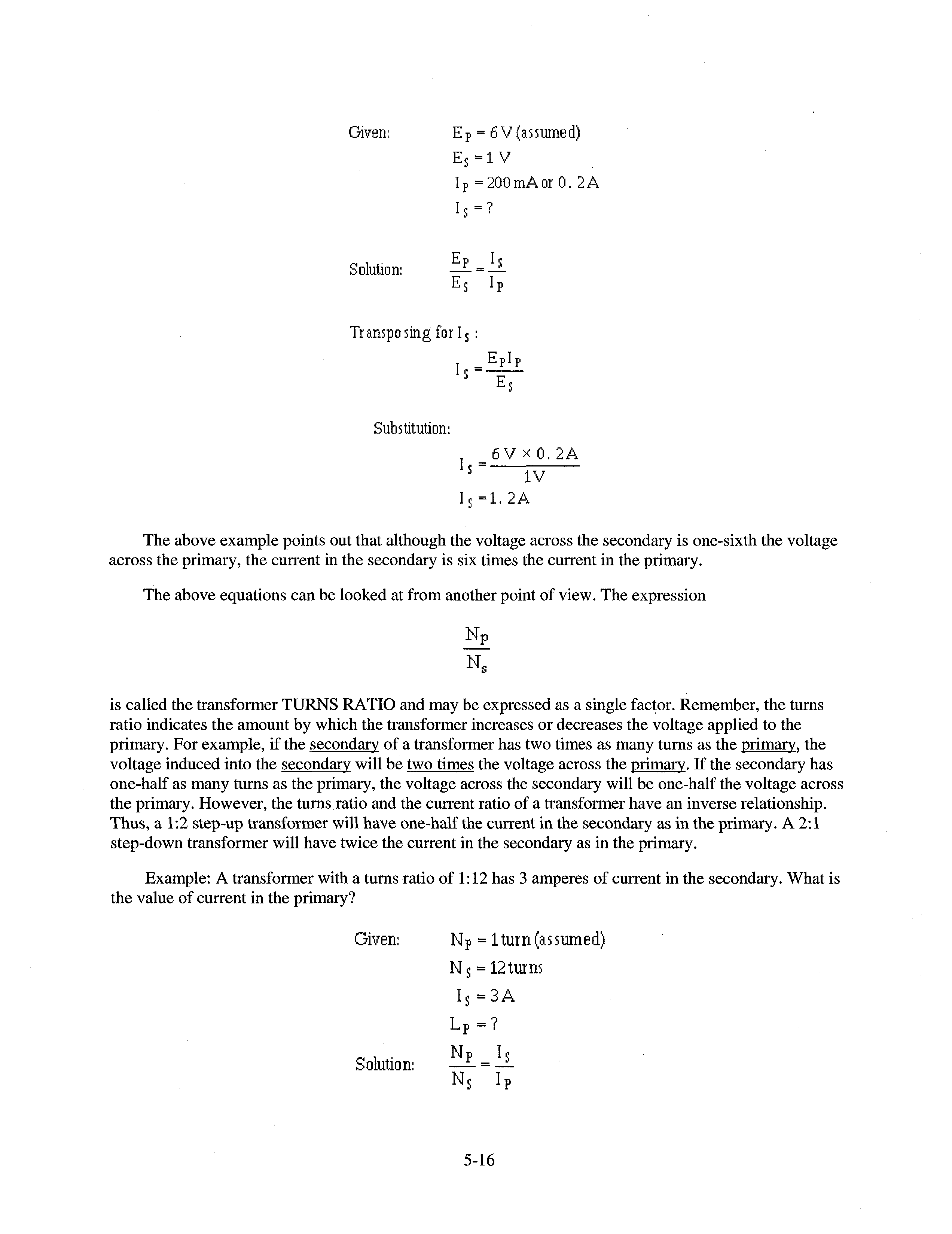


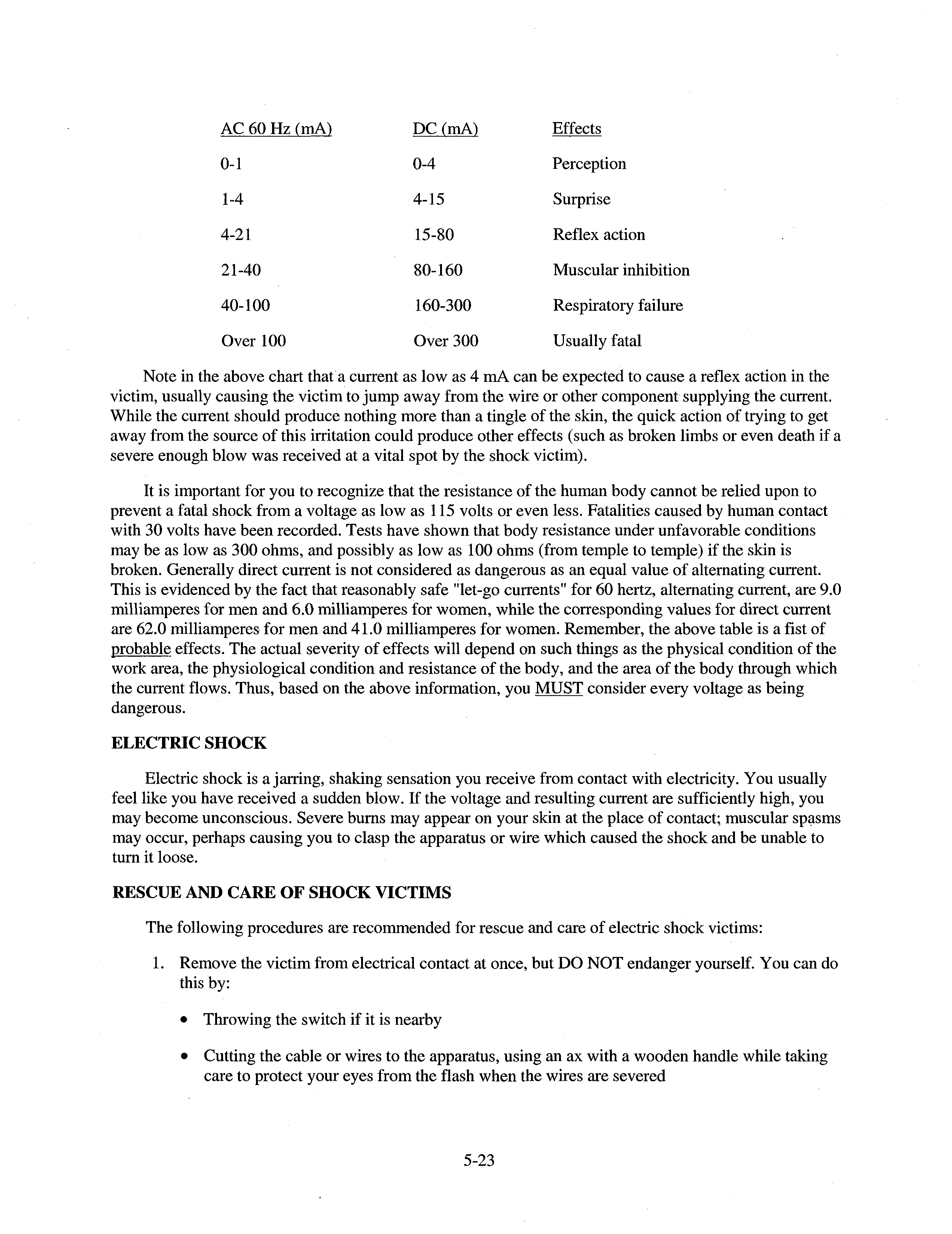


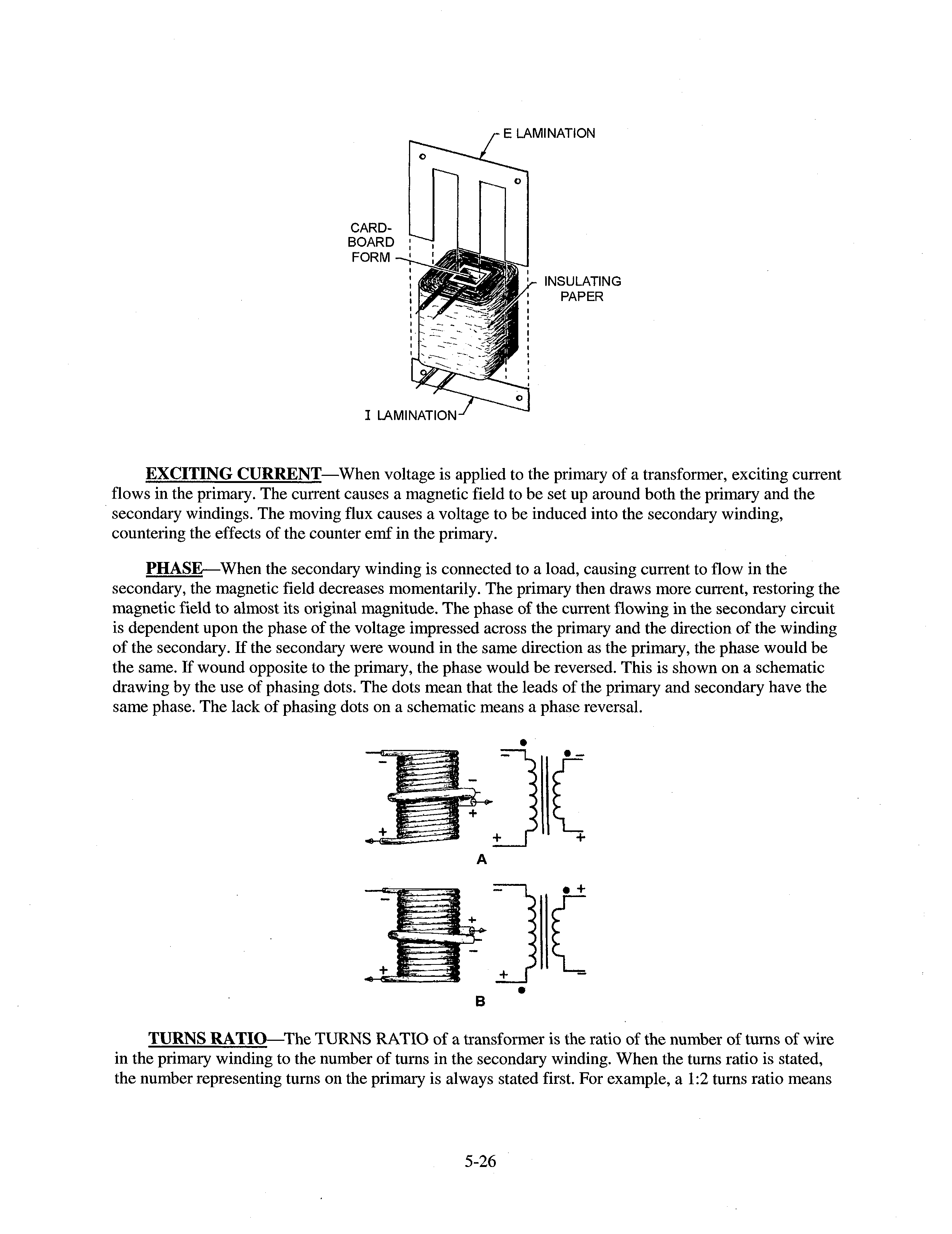
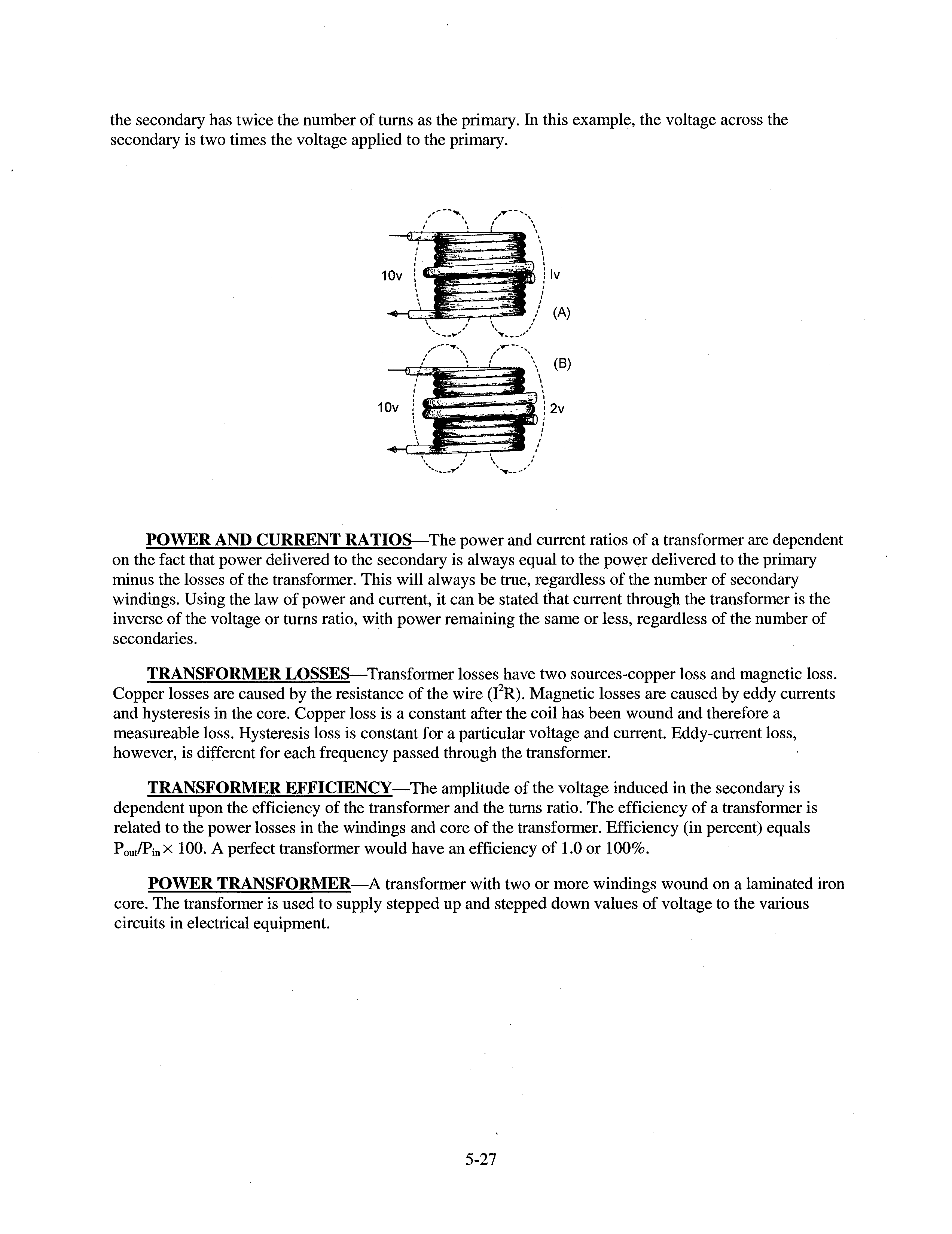


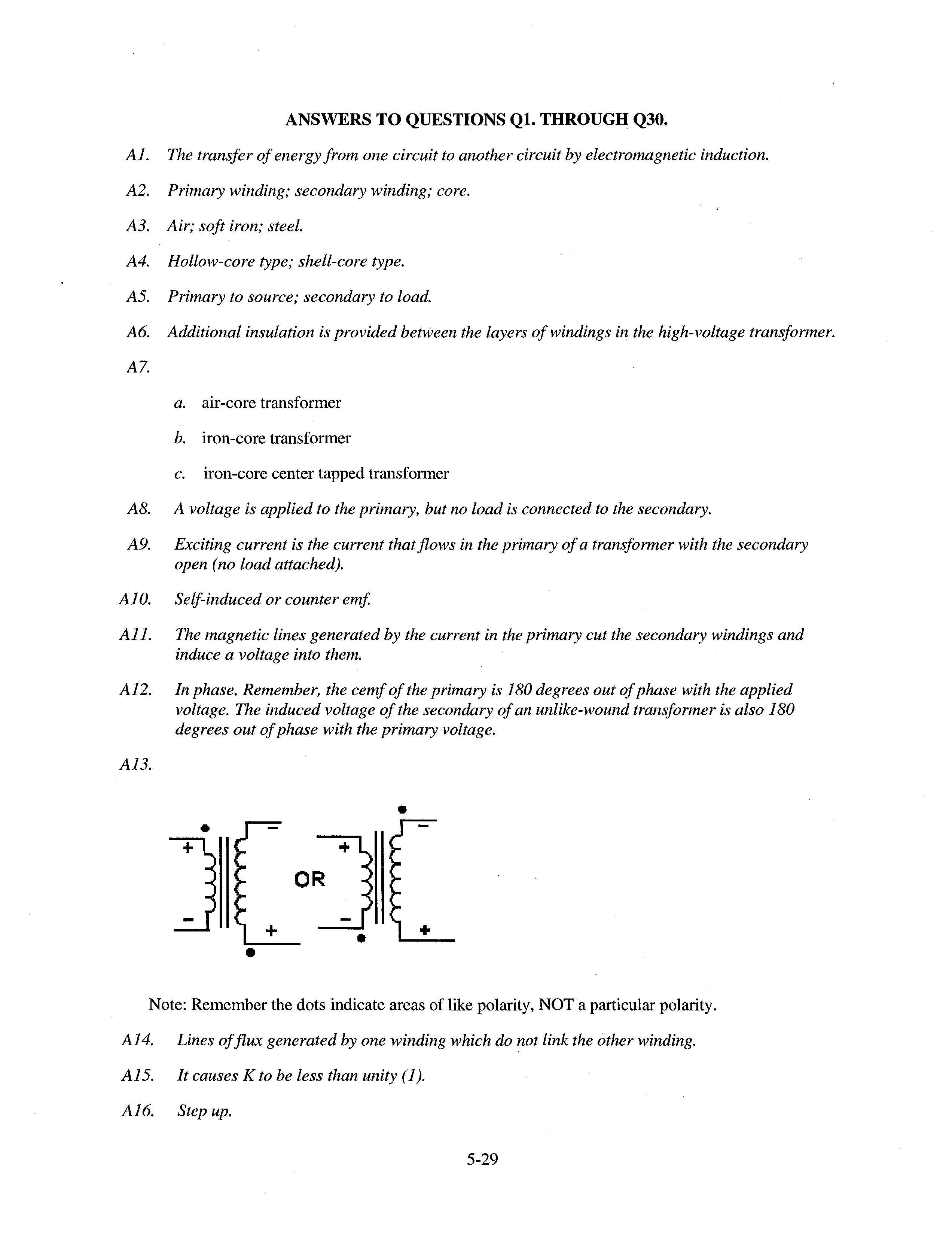
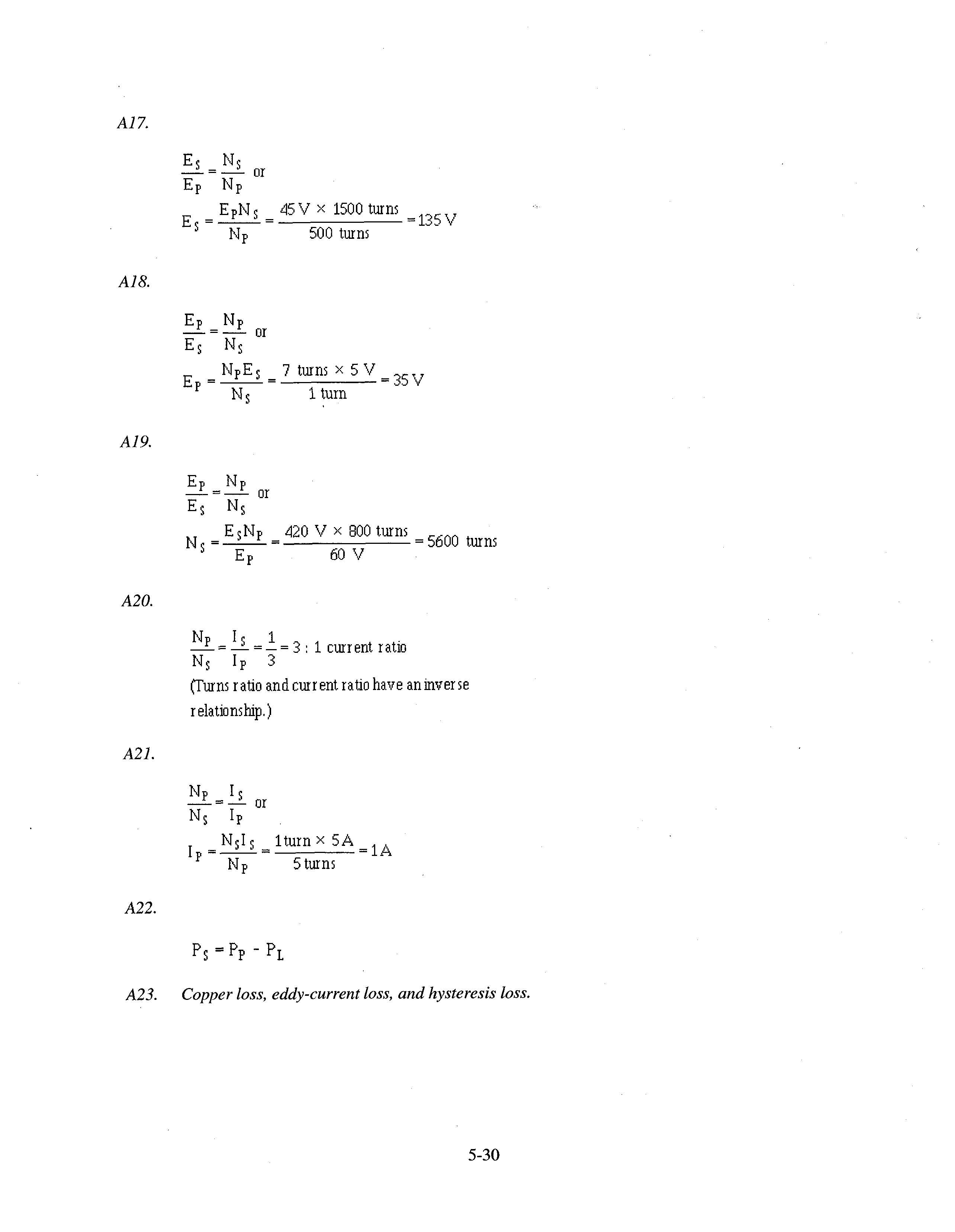
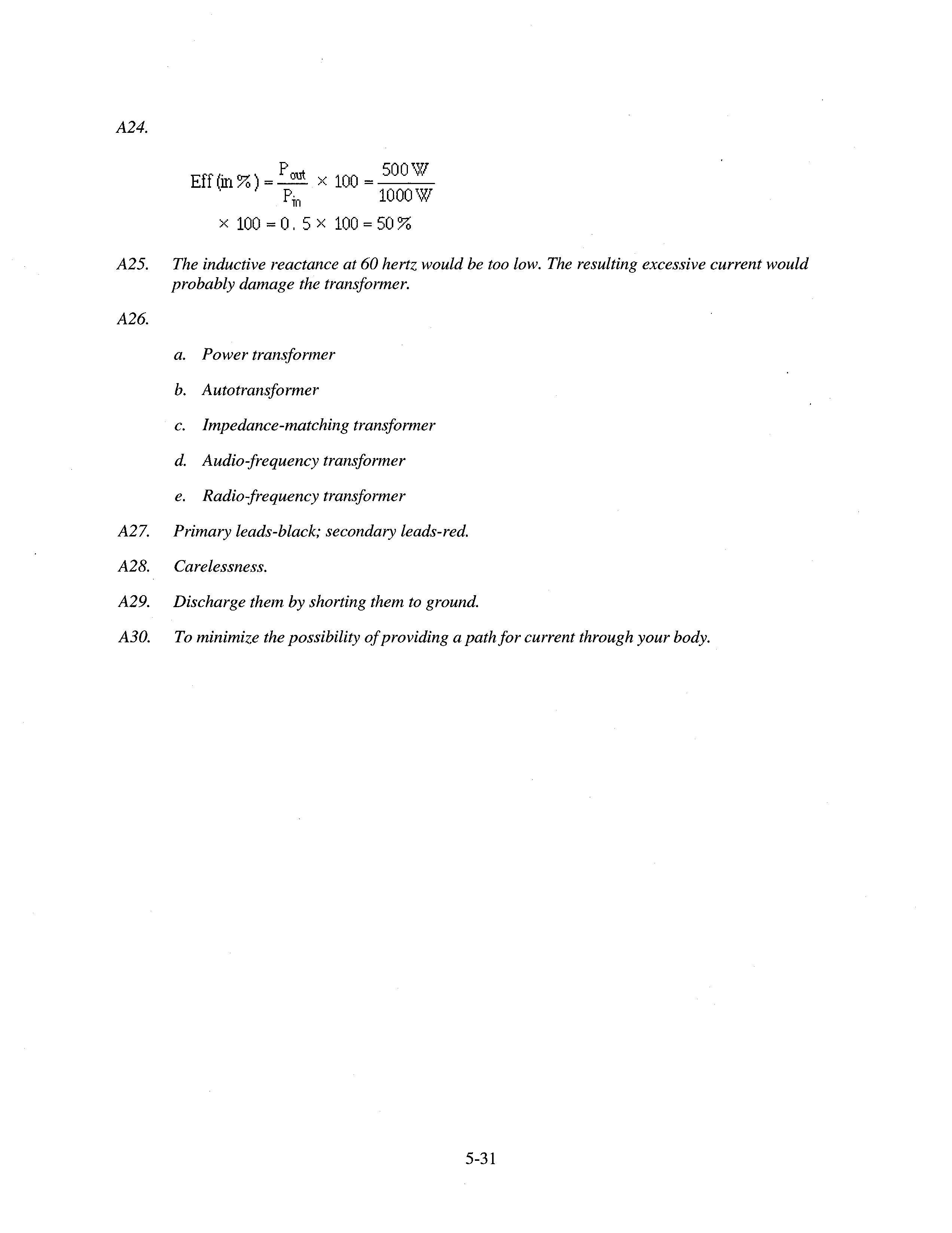


AI-1
APPENDIX I
GLOSSARY
AIR-CORE TRANSFORMER—A transformer composed of two or more coils, which are wound around a non-metallic core.
ALTERNATING CURRENT—An electrical current which constantly changes amplitude and changes polarity at regular intervals.
APPARENT POWER—That power apparently available for use in an ac circuit containing a reactive element. It is the product of effective voltage times effective current expressed in voltamperes. It must be multiplied by the power factor to obtain true power available.
AVERAGE VALUE OF AC—The average of all the instantaneous values of one-half cycle of alternating current.
CAPACITANCE—The property of an electrical circuit that opposes changes in voltage.
CAPACITOR—An electrical device capable of storing electrical energy in an electrostatic field.
CAPACITIVE REACTANCE—The opposition offered to the flow of an alternating current by capacitance, expressed in ohms. The symbol for capacitive reactance is Xc.
CHARGE CYCLE—The period of time that a capacitor in an electrical circuit is storing a charge.
COIL—An inductive device created by looping turns of wire around a core.
COPPER LOSS (I2R LOSS)—The power lost due to the resistance of the conductors. In transformers the power lost due to heating because of current flow (I) through the resistance (R) of the windings.
CORE—Any material that affords a path for magnetic flux lines in a coil.
COUNTER EMF—Counter electromotive force; an electromotive force (voltage) induced in a coil that opposes the applied voltage.
COUPLING, COEFFICIENT OF—An expression of the extent to which two inductors are coupled by magnetic lines of force. This is expressed as a decimal or percentage of maximum possible coupling and represented by the letter K.
CYCLE—One complete positive and one complete negative alternation of a current or voltage.
DIELECTRIC—An insulator; a term applied to the insulating material between the plates of a capacitor.
DIELECTRIC CONSTANT—The ratio of the capacitance of a capacitor with a dielectric between the electrodes to the capacitance of a capacitor with air between the electrodes.
DIELECTRIC HYSTERESIS LOSS—Power loss of a capacitor due to the changes in orientation of electron orbits in the dielectric caused by rapid reversal in polarity of line voltage. The higher the frequency, the greater the loss.
AI-2
DIELECTRIC LEAKAGE—Power loss of a capacitor due to the leakage of current through the dielectric. Also relates to leakage resistance, the higher the leakage resistance, the lower the dielectric leakage.
DISPLACEMENT CURRENT—The current which appears to flow through a capacitor.
EDDY CURRENT—Induced circulating currents in a conducting material that are caused by a varying magnetic field.
EDDY CURRENT LOSS—Losses caused by random current flowing in the core of a transformer. Power is lost in the form of heat.
EFFECTIVE VALUE—Same as root-mean-square.
ELECTROMAGNETIC INDUCTION—The production of a voltage in a coil due to the change in the number of magnetic lines of force (flux linkage) passing through the coil.
ELECTROMAGNETISM—The generation of a magnetic field around a current carrying conductor.
ELECTROMOTIVE FORCE (emf)—The force (voltage) that produces an electric current in a circuit ELECTROSTATIC FIELD—The field of influence between two charged bodies.
EXCITING CURRENT—The current that flows in the primary winding of a transformer, which produces a magnetic flux field. Also called magnetizing current.
FARAD—The basic unit of capacitance. A capacitor has a capacitance of 1 farad when a voltage change of 1 volt per second across it produces a current of 1 ampere.
FLUX—Electrostatic or magnetic lines of force.
FREQUENCY (f)—The number of complete cycles per second existing in any form of wave motion; such as the number of cycles per second of an alternating current.
HENRY (H)—The electromagnetic unit of inductance or mutual inductance. The inductance of a circuit is 1 henry when a current variation of 1 ampere per second induces 1 volt. It is the basic unit of inductance. In radio, smaller units are used such as the millihenry (mH), which is one-thousandth of � ����� ��� �� ��� ���� ����� � �� ���� �� ������� ��� � � ������
HERTZ (Hz)—The basic unit of frequency equal to one cycle per second. HYSTERESIS—The time lag of the magnetic flux in a magnetic material behind the magnetizing force
producing it, caused by the molecular friction of the molecules trying to align themselves with the magnetic force applied to the material.
HYSTERESIS LOSS—The power loss in an iron-core transformer or other alternating-current device as a result of magnetic hysteresis.
IMPEDANCE—The total opposition offered to the flow of an alternating current. It may consist of any combination of resistance, inductive reactance, and capacitive reactance. The symbol for impedance is Z.
IN PHASE—Applied to the condition that exists when two waves of the same frequency pass through their maximum and minimum values of like polarity at the same instant.
AI-3
INDUCTANCE—The property of a circuit which tends to oppose a change in the existing current flow. The symbol for inductance is L.
INDUCTIVE COUPLING—Coupling of two coils by means of magnetic lines of force. In transformers, coupling applied through magnetic lines of force between the primary and secondary windings.
INDUCTIVE REACTANCE—The opposition to the flow of an alternating current caused by the inductance of a circuit, expressed in ohms. Identified by the letter X
L.
INSTANTANEOUS VALUE—The magnitude at any particular instant when a value is continually varying with respect to time.
LAG—The amount one wave is behind another in time; expressed in electrical degrees.
LAMINATED CORE—A core built up from thin sheets of metal insulated from each other and used in transformers.
LEAD—The opposite of lag. Also a wire or connection.
LEAKAGE FLUX—Magnetic flux lines produced by the primary winding which do not link the turns of the secondary winding.
LEAKAGE RESISTANCE—The electrical resistance which opposes the flow of current through the dielectric of a capacitor. The higher the leakage resistance the slower the capacitor will discharge or leak across the dielectric.
LEFT-HAND-RULE FOR GENERATORS—A rule or procedure used to determine the direction of electron current flow in the windings of a generator.
LENZ’S LAW—The current induced in a circuit due to its motion in a magnetic field or to a change in its magnetic flux in such a direction as to exert a mechanical force opposing the motion or to oppose the change in flux.
MAGNETIC FIELD—Region in which the magnetic forces created by a permanent magnet or by a current-carrying conductor or coil can be detected.
MAGNETIC LINES OF FORCE—Imaginary lines used for convenience to designate the direction in which magnetic forces are acting as a result of magneto-motive force.
MUTUAL FLUX—The total flux in the core of a transformer that is common to both the primary and secondary windings. The flux links both windings.
MUTUAL INDUCTANCE—A circuit property existing when the relative position of two inductors causes the magnetic lines of force from one to link with the turns of the other. The symbol for mutual inductance is M.
NEGATIVE ALTERNATION—The negative half of an ac waveform
NO-LOAD CONDITION—The condition that exists when an electrical source or secondary of a transformer is operated without an electrical load.
PEAK-TO-PEAK—The measure of absolute magnitude of an ac waveform, measured from the greatest positive alternation to greatest negative alternation.
AI-4
PEAK VALUE—The maximum instantaneous value of a varying current, voltage, or power. It is equal to 1.414 times the effective value of a sine wave.
PERIOD TIME—The time required to complete one cycle of a waveform.
PHASE—The angular relationship between two alternating currents or voltages when the voltage or current is plotted as a function of time. When the two are in phase, the angle is zero, and both reach their peak simultaneously. When out of phase, one will lead or lag the other; at the instant when one is at its peak, the other will not be at peak value and (depending on the phase angle) may differ in polarity as well as magnitude.
PHASE ANGLE—The number of electrical degrees of lead or lag between the voltage and current waveforms in an ac circuit.
PHASE DIFFERENCE—The time in electrical degrees by which one wave leads or lags another.
POLARIZATION—The magnetic orientation of molecules in a magnetizable material in a magnetic field, whereby tiny internal magnets tend to line up in the field.
POSITIVE ALTERNATION—The positive half of an ac waveform.
POWER FACTOR—The ratio of the actual power of an alternating or pulsating current, as measured by a wattmeter, to the apparent power, as indicated by ammeter and voltmeter readings. The power factor of an inductor, capacitor, or insulator is an expression of their losses
POWER LOSS—The electrical power supplied to a circuit that does no work, usually dissipated as heat.
PRIMARY WINDING—The winding of a transformer connected to the electrical source.
Q—Figure of merit of efficiency of a circuit or coil. Ratio of inductive reactance to resistance in servos. Relationship between stored energy (capacitance) and rate of dissipation in certain types of electric elements, structures, or materials.
RADIO FREQUENCY (RF)—Any frequency of electrical energy capable of propagation into space. RATIO—The value obtained by dividing one number by another, indicating their relative proportions.
RC CONSTANT—Time constant of a resistor-capacitor circuit; equal in seconds to the resistance value in ohms multiplied by the capacitance value in farads.
REACTANCE—The opposition offered to the flow of an alternating current by the inductance, capacitance, or both, in any circuit.
RESONANCE—The condition existing in a circuit when the values of inductance, capacitance, and the applied frequency are such that the inductive reactance and capacitive reactance cancel each other.
RLC CIRCUIT—An electrical circuit which has the properties of resistance, inductance, and capacitance.
RMS—Abbreviation of Root Mean Square.
ROOT MEAN SQUARE (RMS)—The equivalent heating value of an alternating current or voltage, as compared to a direct current or voltage. It is 0.707 times the peak value of a sine wave.
SECONDARY—The output coil of a transformer.


AI-5
SELF-INDUCTION—The production of a counter-electromotive force in a conductor when its own magnetic field collapses or expands with a change in current in the conductor
SINE WAVE—The curve traced by the projection on a uniform time scale of the end of a rotating arm, or vector. Also known as a sinusoidal wave.
THETA—The greek letter ( ) used to represent phase angle. TIME CONSTANT—The time required to charge a capacitor to 63.2 percent of maximum voltage or
discharge to 36.8 percent of its final voltage. The time required for the current in an inductor to increase to 63.2 percent of maximum current or decay to 36.8 percent of its final current.
TRANSFORMER—A device composed of two or more coils, linked by magnetic lines of force, used to transfer electrical energy from one circuit to another.
TRANSFORMER EFFICIENCY—The ratio of output power to input power, generally expressed as a percentage.
TRANSFORMER, STEP-DOWN—A transformer so constructed that the number of turns in the secondary winding is less than the number of turns in the primary winding. This construction will provide less voltage in the secondary circuit than in the primary circuit.
TRANSFORMER, STEP-UP—A transformer so constructed that the number of turns in the secondary winding is more than the number of turns in the primary winding. This construction will provide more voltage in the secondary circuit than in the primary circuit.
TRUE POWER—The power dissipated in the resistance of the circuit, or the power actually used in the circuit.
TURN—One complete loop of a conductor about a core.
TURNS RATIO—The ratio of number of turns in the primary winding to the number of turns in the secondary winding of a transformer.
UNIVERSAL TIME CONSTANT CHART—A chart used to find the time constant of a circuit if the impressed voltage and the values of R and C or R and L are known.
WAVEFORM—The shape of the wave obtained when instantaneous values of an ac quantity are plotted against time in rectangular coordinates.
WAVELENGTH ( )—The distance, usually expressed in meters, traveled by a wave during the time interval of one complete cycle. It is equal to the velocity of light divided by the frequency.
WORKING VOLTAGE—The maximum voltage that a capacitor may operate at without the risk of damage.
VAR—Abbreviation for Volt-Amperes Reactive.
VECTOR—A line used to represent both direction and magnitude.


AII-1
APPENDIX II
GREEK ALPHABET
Name Upper Case
Lower Case
Designates
Alpha……. A � Angles.
Beta……... B Angles, flux density. Gamma….. Conductivity. Delta…….. Variation of a quantity, increment. Epsilon…... E Base of natural logarithms (2.71828). Zeta……… Z Impedance, coefficients, coordinates. Eta………. H Hysteresis coefficient, efficiency, magnetizing force. Theta…….. Phase angle. Iota………. I /
Kappa…… K .
Dielectric constant, coupling coefficient, susceptibility.
Lambda….. Wavelength. Mu………. M Permeability, micro, amplification factor. Nu……….. N Reluctivity. Xi………...
Omicron…. Pi………... 3.1416 Rho……… P Resistivity. Sigma……. Tau………. T Time constant, time-phase displacement. Upsilon….. Phi………. Angles, magnetic flux. Chi………. X Psi……….. Dielectric flux, phase difference. Omega… ���� ������ ����� ������� ��� ���� �! �� �� "�� ������
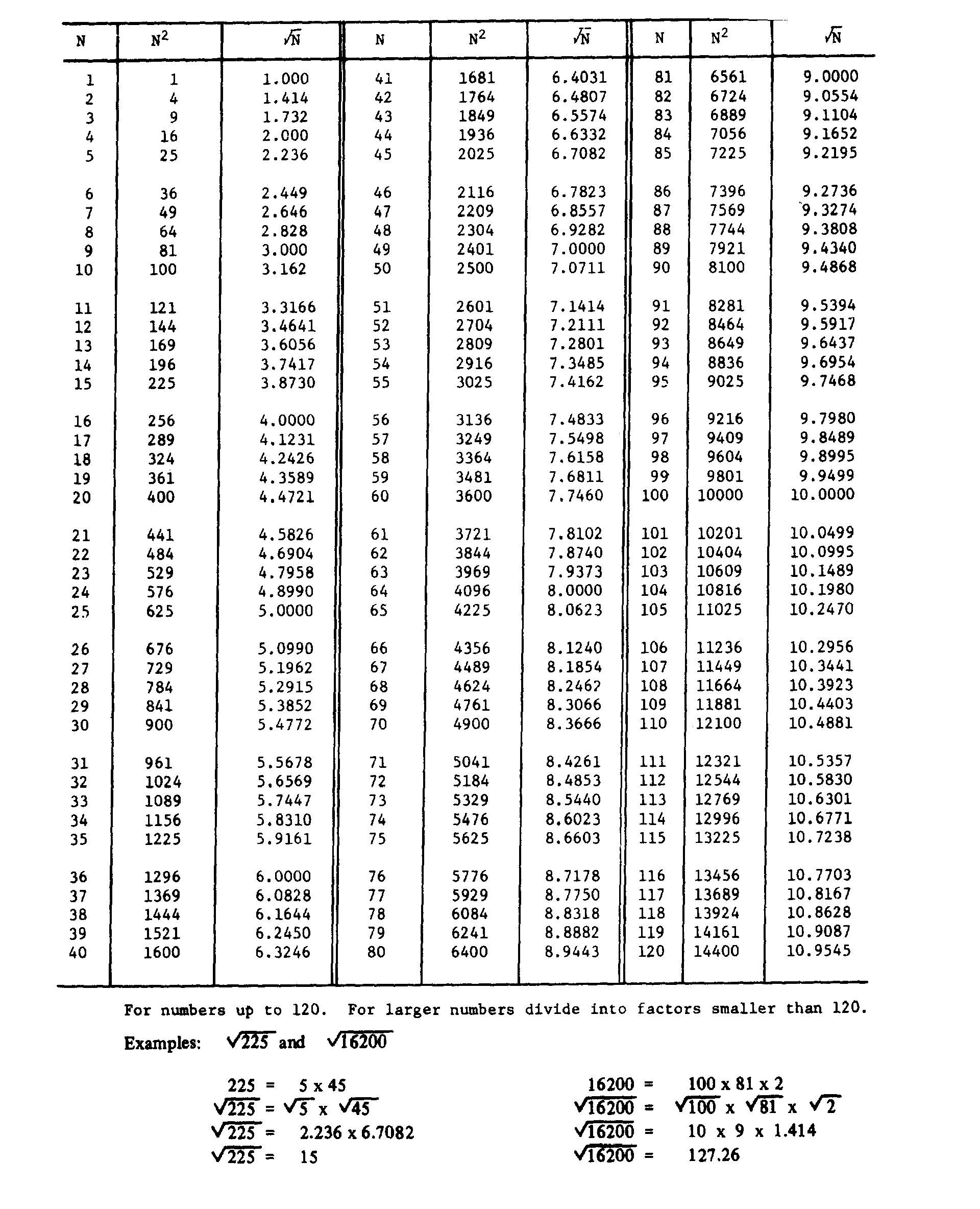


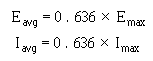
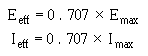
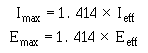
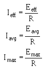
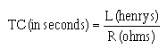
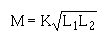
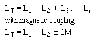
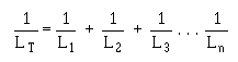
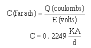
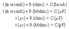
AIV-1
APPENDIX IV
USEFUL AC FORMULAS PERIOD TIME (t)
FREQUENCY (f)
AVERAGE VOLTAGE OR CURRENT
EFFECTIVE VALUE OF VOLTAGE OR CURRENT
MAXIMUM VOLTAGE OR CURRENT
OHM’S LAW OF AC CIRCUIT CONTAINING ONLY RESISTANCE
L/R TIME CONSTANT (TC)
MUTUAL INDUCTANCE (M)
TOTAL INDUCTANCE (LT) Series without magnetic coupling
TOTAL INDUCTANCE (LT) PARALLEL (No magnetic coupling)
CAPACITANCE (C)
RC TIME CONSTANT (t)
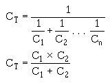
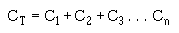


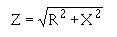
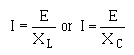

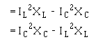
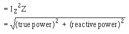
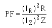


AIV-2
TOTAL CAPACITANCE (CT) SERIES
TOTAL CAPACITANCE (CT) PARALLEL
INDUCTIVE REACTANCE (XL)
CAPACITIVE REACTANCE (XC)
IMPEDANCE (Z)
OHM’S LAW FOR REACTIVE CIRCUITS
OHM’S LAW FOR CIRCUITS CONTAINING RESISTANCE AND REACTANCE
REACTIVE POWER
APPARENT POWER
POWER FACTOR (PF)
VOLTAGE ACROSS THE SECONDARY (Es)
VOLTAGE ACROSS THE PRIMARY (Ep)
CURRENT ACROSS THE SECONDARY (Is)
CURRENT ACROSS THE PRIMARY (Ip)
TRANSFORMER EFFICIENCY

Figure V-1.—A right triangle.
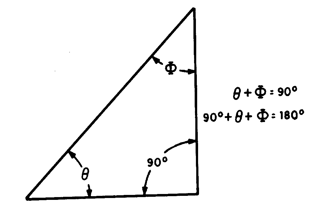
AV-1
APPENDIX V
TRIGONOMETRIC FUNCTIONS
In a right triangle, there are several relationships which always hold true. These relationships pertain to the length of the sides of a right triangle, and the way the lengths are affected by the angles between them. An understanding of these relationships, called trigonometric functions, is essential for solving problems in a-c circuits such as power factor, impedance, voltage drops, and so forth.
To be a RIGHT triangle, a triangle must have a "square" corner; one in which there is exactly 90º between two of the sides. Trigonometric functions do not apply to any other type of triangle. This type of triangle is shown in figure V-1.
By use of the trigonometric functions, it is possible to determine the UNKNOWN length of one or more sides of a triangle, or the number of degrees in UNKNOWN angles, depending on what is presently known about the triangle. For instance, if the lengths of any two sides are known, the third side and both angles � ������� �� ����� ��� �� �������� � #�� �������� ��� ��� �� � ��� �� ��� ������ � ��� �� side and one of the angles( � � �� ���� $%�� ��� &� "��
The first basic fact of triangles is that IN ANY RIGHT TRIANGLE, THE SUM OF THE THREE ANGLES FORMED INSIDE THE TRIANGLE MUST ALWAYS EQUAL 180º . If one angle is always 90º (a right angle) then the sum of the other two angles must always be 90º .
thus, if angle � �� &� "� ��� �� ����&�� �������� �
For instance, if ; is 30º � "��� �� '
Figure V-2.—A 30º - 60º - 90º triangle.
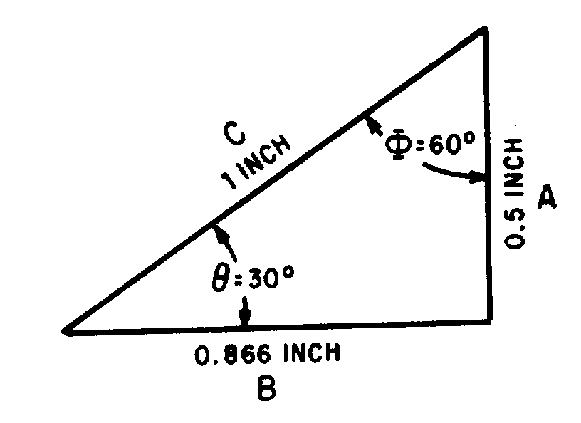
AV-2
Also, if �� &� "� ��� �� �������� �� ��� ���� �������
The second basic fact you must understand is that FOR EVERY DIFFERENT COMBINATION OF ANGLES IN A TRIANGLE, THERE IS A DEFINITE RATIO BETWEEN THE LENGTHS OF THE THREE SIDES. Consider the triangle in figure V-2, consisting of the base, side B; the altitude, side A; and the hypotenuse, side C. (The hypotenuse is always the longest side, and is always opposite the 90º angle.)
If angle �is 30º ���� �� (�º . With �equal to 30º , the ratio of the length of side B to side C is 0.866 to 1. That is, if the hypotenuse is 1 inch long, the side adjacent to , side B, is 0.866 inch long. Also, with �equal to 30º , the ratio of side A to side C is 0.5 to 1. That is, with the hypotenuse 1 inch long, the side opposite to � (side A) is 0.5 inch long. With still at 30º , side A is 0.5774 of the length of B. With the combination of angles given (30º -60º -90º ) these are the ONLY ratios of lengths that will "fit" to form a right triangle.
Note that three ratios are shown to exist for the given value of : the ratio B\C which is always referred to as the COSINE ratio of , the ratio A\C, which is always the SINE ratio of , and the ratio A\B, which is always the TANGENT ratio of . If changes, all three ratios change, because the lengths of the sides (base and altitude) change. There is a set of ratios for every increment between 0º and 90º . These angular ratios, or sine, cosine, and tangent functions, are listed for each degree and tenth of degree in a table at the end of this appendix. In this table, the length of the hypotenuse of a triangle is considered fixed. Thus, the ratios of length given refer to the manner in which sides A and B vary with relation to each other and in relation to side C, as angle is varied from 0º to 90º .
The solution of problems in trigonometry (solution of triangles is much simpler when the table of trigonometric functions is used properly. The most common ways in which it is used will be shown by solving a series of exemplary problems.
Figure V-3.—Problem 1.
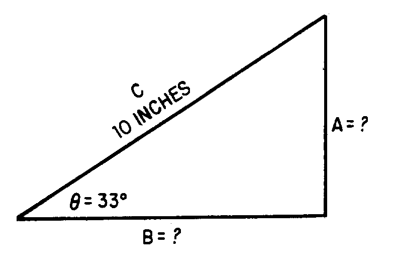
Figure V4.—Problem 2.
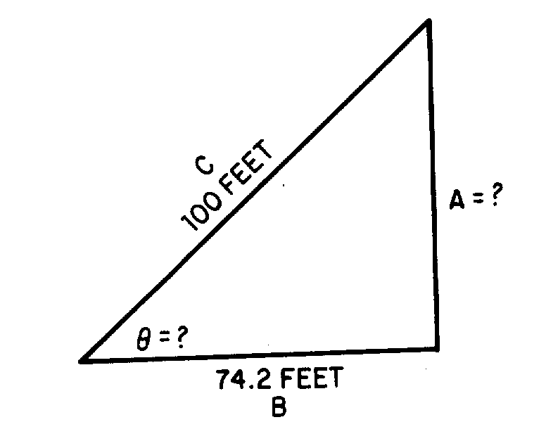
AV-3
Problem 1: If the hypotenuse of the triangle (side C) in figure V-3 is 10 inches long, and angle is 33º , how long are sides B and A?
Solution: The ratio B/C is the cosine function. By checking the table of functions, you will find that the cosine of 33º is 0.8387. This means that the length of B is 0.8387 the length of side C. If side C is 10 inches long, then side B must be 10 × 0.8387, or 8.387 inches in length. To determine the length of side A, use the sine function, the ratio A\C. Again consulting the table of functions, you will find that the sine of 33º is 0.5446. Thus, side A must be 10 × 0.5446, or 5.446 inches in length.
Problem 2: The triangle in figure V-4 has a base 74.2 feet long, and hypotenuse 100 feet long. What is � and how long is side A?
Solution: When no angles are given, you Must always solve for a known angle first. The ratio B\C is the cosine of the unknown angle ; therefore 74.2/100 or 0.742, is the cosine of the unknown angle. Locating 0.742 as a cosine value in the table, you find that it is the cosine of 42.1º . That is, � = 42.1º . With known, side A is solved for by use of the sine ratio A/C. The sine of 42.1º , according to the table, is 0.6704. Therefore, side A is 100 × 0.6704, or 67.04 feet long.
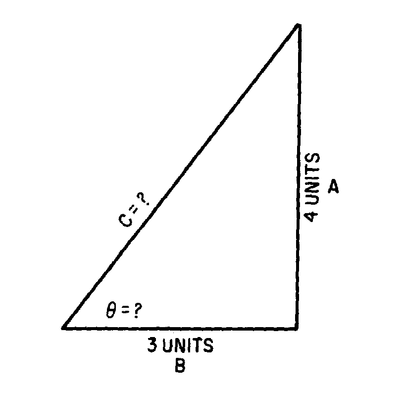
Figure V-5.—Problem 3.
AV-4
Problem 3: In the triangle in figure V-5, the base is 3 units long, and the altitude is 4 units. What is , and how long is the hypotenuse?
Solution: With the information given, the tangent of may be determined. Tan = A/B = 4/3 = 1.33.
Locating the value 1.33 as a tangent value in the table of functions, you find it to be the tangent of 53.1º . Therefore, = 53.1º . Once is known, either the sine or cosine ratio may be used to determine the length of the hypotenuse. The cosine of 53.1º is 0.6004. This indicates that the base of 3 units is 0.6004, the length of the hypotenuse. Therefore, the hypotenuse is 3/0.6004, or 5 units in length. Using the sine ratio, the hypotenuse is 4/0.7997, or 5 units in length.
In the foregoing explanations and problems, the sides of triangles were given in inches, feet, and units. In applying trigonometry to a-c circuit problems, these units of measure will be replaced by such values given in ohms, amperes, volts, and watts. Angle �will be the phase angle between (source) voltage and circuit current. However, the solution of these a-c problems is accomplished in exactly the same manner as the foregoing problems. Only the units and some terminology are changed.
AVI-2
deg sin cos tan cot deg sin cos tan cot 0.0 0.0000 1.0000 0.00000 90.0 4.0 0.6976 0.9976 0.6993 140.301 86.0 0.1 0.0175 1.0000 0.00175 573.0 0.9 0.1 0.7150 0.9974 0.7168 130.951 0.9 0.2 0.0349 1.0000 0.00349 286.5 0.8 0.2 0.7324 0.9973 0.7344 130.617 0.8 0.3 0.0524 1.0000 0.00524 191.0 0.7 0.3 0.7498 0.9972 0.17519 130.30 0.7 0.4 0.0698 1.0000 0.00698 143.24 0.6 0.4 0.7672 0.9971 0.7695 120.996 0.6 0.5 0.0873 1.0000 0.00873 114.59 0.5 0.5 0.7846 0.9969 0.7870 120.706 0.5 0.6 0.1047 0.9999 0.10147 95.49 0.4 0.6 0.8020 0.9968 0.8046 120.429 0.4 0.7 0.1222 0.9999 0.01222 81.85 0.3 0.7 0.8194 0.9966 0.8221 120.163 0.3 0.8 0.1396 0.9999 0.01396 71.62 0.2 0.8 0.8368 0.9965 0.8397 110.909 0.2 0.9 0.1571 0.9999 0.01571 63.66 0.1 0.9 0.8542 0.9963 0.8573 110.664 0.1
1.0 0.1745 0.9998 0.1746 570.20 89.0 5.0 0.8716 0.9962 0.8749 110.430 85.0 0.1 0.1920 0.9998 0.1920 520.8 0.9 0.1 0.8889 0.9960 0.89215 110.205 0.9 0.2 0.2094 0.9998 0.2095 470.74 0.8 0.2 0.9063 0.9959 0.9101 10.988 0.8 0.3 0.2269 0.9997 0.2269 440.7 0.7 0.3 0.9237 0.9957 0.9277 10.780 0.7 0.4 0.2443 0.9997 0.2444 40.92 0.6 0.4 0.9411 0.9956 0.9453 10.579 0.6 0.5 0.2618 0.9997 0.2619 380.19 0.5 0.5 0.9585 0.9954 0.9629 10.385 0.5 0.6 0.2792 0.9996 0.2793 350.80 0.4 0.6 0.9758 0.9952 0.9805 10.199 0.4 0.7 0.2967 0.9996 0.2968 330.69 0.4 0.7 0.9932 0.9951 0.9981 10.19 0.3 0.8 0.3141 0.9995 0.3143 310.82 0.2 0.8 0.10106 0.9949 0.10158 90.845 0.2 0.9 0.3316 0.9995 0.3317 30.14 0.1 0.9 0.10279 0.9947 0.10334 90.677 0.1
2.0 0.3490 0.9994 0.3492 280.64 88.0 6.0 0.10453 0.9945 0.10510 90.514 84.0 0.1 0.3664 0.9993 0.3667 270.27 0.9 0.1 0.10626 0.9943 0.10687 90.357 0.9 0.2 0.3839 0.9993 0.3842 260.3 0.8 0.2 0.1080 0.9942 0.10863 90.205 0.8 0.3 0.4013 0.9992 0.4016 240.90 0.7 0.3 0.10973 0.9940 0.11040 90.58 0.7 0.4 0.4188 0.9991 0.4191 230.86 0.6 0.4 0.11147 0.9938 0.11217 80.915 0.6 0.5 0.4362 0.9990 0.4366 220.90 0.5 0.5 0.11320 0.9936 0.11394 80.777 0.5 0.6 0.4536 0.9990 0.4541 220.2 0.4 0.6 0.11494 0.9934 0.11570 80.643 0.4 0.7 0.4711 0.9989 0.4716 210.20 0.3 0.7 0.11667 0.9932 0.11747 80.513 0.3 0.8 0.4885 0.9988 0.4891 20.45 0.2 0.8 0.11840 0.9930 0.11924 80.386 0.2 0.9 0.5059 0.9987 0.5066 190.74 0.1 0.9 0.12014 0.9928 0.12101 80.264 0.1
3.0 0.5234 0.9986 0.5241 190.81 87.0 7.0 0.12187 0.9925 0.12278 80.144 83.0 0.1 0.5408 0.9985 0.5416 180.464 0.9 0.1 0.12360 0.9923 0.12456 80.28 0.9 0.2 0.5582 0.9984 0.5591 170.886 0.8 0.2 0.12533 0.9921 0.12633 70.916 0.8 0.3 0.5756 0.9983 0.5766 170.343 0.7 0.3 0.12706 0.9919 0.12810 70.806 0.7 0.4 0.5931 0.9982 0.5941 160.832 0.6 0.4 0.12880 0.9917 0.12988 70.70 0.6 0.5 0.6105 0.9981 0.6116 160.350 0.5 0.5 0.13053 0.9914 0.13165 70.596 0.5 0.6 0.6279 0.9980 0.6291 150.895 0.4 0.6 0.13226 0.9912 0.13343 70.495 0.4 0.7 0.6453 0.9979 0.6467 150.464 0.3 0.7 0.13399 0.9910 0.13521 70.396 0.3 0.8 0.6627 0.9978 0.6642 150.56 0.2 0.8 0.13572 0.9907 0.13698 70.30 0.2 0.9 0.6802 0.9977 0.6817 140.669 0.1 0.9 0.13744 0.9905 0.13876 70.207 0.1
cos sin cot tan deg cos sin cot tan
AVI-3
deg sin cos tan cot deg sin cos tan cot 8.0 0.13917 0.9903 0.14054 70.115 82.0 12.0 0.2079 0.9781 0.2126 40.705 78.0 0.1 0.14090 0.990 0.14232 70.26 0.9 0.1 0.2096 0.9778 0.2144 40.665 0.9 0.2 0.14263 0.9898 0.14410 60.940 0.8 0.2 0.2133 0.9774 0.2162 40.625 0.8 0.3 0.14436 0.9895 0.14588 60.855 0.7 0.3 0.2130 0.9770 0.2180 40.586 0.7 0.4 0.14608 0.9893 0.14767 60.772 0.6 0.4 0.2147 0.9767 0.2199 40.548 0.6 0.5 0.14781 0.9890 0.14945 60.691 0.5 0.5 0.2164 0.9763 0.2217 40.511 0.5 0.6 0.14954 0.9888 0.15124 60.612 0.4 0.6 0.2181 0.9759 0.2235 40.474 0.4 0.7 0.15126 0.9885 0.15302 60.535 0.3 0.7 0.2198 0.9755 0.2254 40.437 0.3 0.8 0.15299 0.9882 0.15481 60.460 0.2 0.8 0.2215 0.9751 0.2272 40.402 0.2 0.9 0.15471 0.9880 0.15660 60.386 0.1 0.9 0.2233 0.9748 0.2290 40.366 0.1
9.0 0.15643 0.9877 0.15836 60.314 81.0 13.0 0.2250 0.9744 0.2309 40.331 77.0 0.1 0.15816 0.9874 0.16017 60.243 0.9 0.1 0.2267 0.9740 0.2327 40.297 0.9 0.2 0.15988 0.9871 0.16196 60.174 0.8 0.2 0.2284 0.9736 0.2345 40.264 0.8 0.3 0.16160 0.9869 0.16376 60.107 0.7 0.3 0.230 0.9732 0.2364 40.230 0.7 0.4 0.16333 0.9866 0.16555 60.41 0.6 0.4 0.2317 0.9728 0.2382 40.198 0.6 0.5 0.16505 0.9863 0.16734 50.976 0.5 0.5 0.2334 0.9724 0.2401 40.165 0.5 0.6 0.16677 0.9860 0.16914 50.912 0.4 0.6 0.2351 0.9720 0.2419 40.134 0.4 0.7 0.16849 0.9857 0.17093 50.850 0.3 0.7 0.2368 0.9715 0.2438 40.102 0.3 0.8 0.17021 0.9854 0.17273 50.789 0.2 0.8 0.2385 0.9711 0.2456 40.71 0.2 0.9 0.17193 0.9851 0.17453 50.730 0.1 0.9 0.2402 0.9707 0.2475 40.41 0.1
10.0 0.1736 0.9848 0.1763 50.671 80.0 14.0 0.2419 0.9703 0.2493 40.11 76.0
0.1 0.1754 0.9845 0.1781 50.614 0.9 0.1 0.2436 0.9699 0.2512 30.981 0.9 0.2 0.1771 0.9842 0.1799 50.558 0.8 0.2 0.2453 0.9694 0.2530 30.952 0.8 0.3 0.1788 0.9839 0.1817 50.503 0.7 0.3 0.2470 0.9680 0.2549 30.923 0.7 0.4 0.1805 0.9836 0.1835 50.449 0.6 0.4 0.2487 0.9686 0.2568 30.895 0.6 0.5 0.1822 0.9833 0.1853 50.396 0.5 0.5 0.2504 0.9681 0.2586 30.867 0.5 0.6 0.1840 0.9829 0.1871 50.343 0.4 0.6 0.2521 0.9677 0.2605 30.839 0.4 0.7 0.1857 0.9826 0.1890 50.292 0.3 0.7 0.2538 0.9673 0.2623 30.812 0.3 0.8 0.1874 0.9823 0.1908 50.242 0.2 0.8 0.2554 0.9668 0.2642 30.785 0.2 0.9 0.1891 0.9820 0.1926 50.193 0.1 0.9 0.2571 0.9664 0.2661 30.758 0.1
11.0 0.1908 0.9816 0.1944 50.145 79.0 15.0 0.2588 0.9659 0.2679 30.732 75.0
0.1 0.1925 0.9813 0.1962 50.97 0.9 0.1 0.2605 0.9655 0.2698 30.706 0.9 0.2 0.1942 0.9810 0.1980 50.50 0.8 0.2 0.2622 0.9650 0.2717 30.681 0.8 0.3 0.1959 0.9806 0.1998 50.5 0.7 0.3 0.2639 0.9646 0.2736 30.655 0.7 0.4 0.1977 0.9803 0.2016 40.959 0.6 0.4 0.2656 0.9641 0.2754 30.630 0.6 0.5 0.1994 0.9799 0.2035 40.915 0.5 0.5 0.2672 0.9636 0.2773 30.606 0.5 0.6 0.2011 0.9796 0.2053 40.872 0.4 0.6 0.2689 0.9632 0.2792 30.582 0.4 0.7 0.2028 0.9792 0.2071 40.829 0.3 0.7 0.2706 0.9627 0.2811 30.558 0.3 0.8 0.2045 0.9789 0.2089 40.787 0.2 0.8 0.2723 0.9622 0.2830 30.534 0.2 0.9 0.2062 0.9785 0.2107 40.745 0.1 0.9 0.2740 0.9617 0.2849 30.511 0.2 cos sin cot tan deg cos sin cot tan deg
AVI-4
deg sin cos tan cot deg sin cos tan cot 16.0 0.2756 0.9613 0.2867 30.487 74.0 20.0 0.3420 0.9397 0.3640 20.747 70.0
0.1 0.2773 0.9608 0.2886 30.465 0.9 0.1 0.3437 0.9391 0.3659 20.733 0.9 0.2 0.2790 0.9603 0.2905 30.442 0.8 0.2 0.3453 0.9385 0.3679 20.718 0.8 0.3 0.2807 0.9598 0.2924 30.420 0.7 0.3 0.3469 0.9379 0.3699 20.703 0.7 0.4 0.2823 0.9593 0.2943 30.398 0.6 0.4 0.3486 0.9373 0.3719 20.689 0.6 0.5 0.2840 0.9588 0.2962 30.376 0.5 0.5 0.3502 0.9367 0.3739 20.675 0.5 0.6 0.2857 0.9583 0.2981 30.354 0.4 0.6 0.3518 0.9361 0.3759 20.660 0.4 0.7 0.2874 0.9578 0.300 30.333 0.3 0.7 0.3535 0.9354 0.3779 20.646 0.3 0.8 0.2890 0.9573 0.3019 30.312 0.2 0.8 0.3551 0.9348 0.3799 20.633 0.2 0.9 0.2907 0.9568 0.3038 30.291 0.1 0.9 0.3567 0.9342 0.3819 20.619 0.1
17.0 0.2924 0.9563 0.3067 30.271 73.0 21.0 0.3584 0.9336 0.3839 20.605 69.0
0.1 0.2940 0.9558 0.3076 30.271 0.9 0.1 0.360 0.9330 0.3859 20.592 0.9 0.2 0.2957 0.9553 0.3096 30.230 0.8 0.2 0.3616 0.9323 0.3879 20.578 0.8 0.3 0.2974 0.9548 0.3115 30.211 0.7 0.3 0.3633 0.9317 0.3899 20.565 0.7 0.4 0.2990 0.9542 0.3134 30.191 0.6 0.4 0.3649 0.9311 0.3919 20.552 0.6 0.5 0.307 0.9537 0.3153 30.172 0.5 0.5 0.3665 0.9304 0.3939 20.539 0.5 0.6 0.3024 0.9532 0.3172 30.152 0.4 0.6 0.3681 0.9298 0.3959 20.526 0.4 0.7 0.3040 0.9527 0.3191 30.133 0.3 0.7 0.3697 0.9291 0.3979 20.513 0.3 0.8 0.3057 0.9521 0.3211 30.115 0.2 0.8 0.3714 0.9285 0.400 20.50 0.2 0.9 0.3074 0.9516 0.3230 30.96 0.1 0.9 0.3730 0.9278 0.4020 20.488 0.1
18.0 0.3090 0.9511 0.3249 30.78 72.0 22.0 0.3746 0.9272 0.4040 20.475 68.0
0.1 0.3107 0.9505 0.3269 30.60 0.9 0.1 0.3762 0.9265 0.4061 20.463 0.9 0.2 0.3123 0.950 0.3288 30.42 0.8 0.2 0.3778 0.9259 0.4081 20.450 0.8 0.3 0.3140 0.9494 0.3307 30.24 0.7 0.3 0.3795 0.9252 0.4101 20.438 0.7 0.4 0.3156 0.9489 0.3327 30.6 0.6 0.4 0.3811 0.9245 0.4122 20.426 0.6 0.5 0.3173 0.9483 0.3346 20.989 0.5 0.5 0.3727 0.9239 0.4142 20.414 0.5 0.6 0.3190 0.9478 0.3365 20.971 0.4 0.6 0.3843 0.9232 0.4163 20.402 0.4 0.7 0.3206 0.9472 0.3385 20.954 0.3 0.7 0.3859 0.9225 0.4183 20.391 0.3 0.8 0.3223 0.9466 0.3404 20.937 0.2 0.8 0.3875 0.9219 0.4204 20.379 0.2 0.9 0.3239 0.9461 0.3424 20.921 0.1 0.9 0.3891 0.9212 0.4224 20.367 0.1
19.0 0.3256 0.9455 0.3443 20.904 71.0 23.0 0.3907 0.9205 0.4245 20.356 67.0
0.1 0.3272 0.9449 0.3463 20.888 0.9 0.1 0.3923 0.9198 0.4265 20.344 0.9 0.2 0.3289 0.9444 0.3482 20.872 0.8 0.2 0.3939 0.9191 0.4286 20.333 0.8 0.3 0.3305 0.9438 0.3502 20.856 0.7 0.3 0.3955 0.9184 0.4307 20.322 0.7 0.4 0.3322 0.9432 0.3522 20.840 0.6 0.4 0.3971 0.9178 0.4327 20.311 0.6 0.5 0.3338 0.9426 0.3541 20.824 0.5 0.5 0.3987 0.9171 0.4348 20.30 0.5 0.6 0.3355 0.9421 0.3561 20.808 0.4 0.6 0.403 0.9164 0.4369 20.289 0.4 0.7 0.3371 0.9415 0.3581 20.793 0.3 0.7 0.4019 0.9157 0.4390 20.278 0.3 0.8 0.3387 0.9409 0.360 20.778 0.2 0.8 0.4035 0.9150 0.4411 20.267 0.2 0.9 0.3403 0.9403 0.3620 20.762 0.1 0.9 0.4051 0.9143 0.4431 20.257 0.1
cos sin cot tan deg cos sin cot tan deg
AVI-5
deg sin cos tan cot deg sin cos tan cot 24.0 0.4067 0.9135 0.4452 20.246 66.0 28.0 0.4695 0.8829 0.5317 10.881 62.0
0.1 0.4083 0.9128 0.4473 20.236 0.9 0.1 0.4710 0.8821 0.5340 10.873 0.9 0.2 0.4099 0.9121 0.4494 20.225 0.8 0.2 0.4726 0.8813 0.5362 10.865 0.8 0.3 0.4115 0.9114 0.4515 20.215 0.7 0.3 0.4741 0.8805 0.5384 10.857 0.7 0.4 0.4131 0.9107 0.4536 20.204 0.6 0.4 0.4756 0.8796 0.5407 10.849 0.6 0.5 0.4147 0.910 0.4557 20.194 0.5 0.5 0.4772 0.8788 0.5430 10.842 0.5 0.6 0.4163 0.9092 0.4578 20.184 0.4 0.6 0.4787 0.8780 0.5452 10.834 0.4 0.7 0.4179 0.9085 0.4599 20.174 0.3 0.7 0.4802 0.8771 0.5475 10.827 0.3 0.8 0.4195 0.9078 0.4621 20.164 0.2 0.8 0.4818 0.8763 0.5498 10.819 0.2 0.9 0.4210 0.9070 0.4642 20.154 0.1 0.9 0.4833 0.8755 0.5520 10.811 0.1
25.0 0.4226 0.9063 0.4663 20.145 65.0 29.0 0.4848 0.8746 0.5543 10.804 61.0
0.1 0.4242 0.9056 0.4684 20.135 0.9 0.1 0.4863 0.8738 0.5566 10.797 0.9 0.2 0.4258 0.9048 0.4706 20.125 0.8 0.2 0.4879 0.8729 0.5589 10.789 0.8 0.3 0.4274 0.9041 0.4727 20.116 0.7 0.3 0.4894 0.8721 0.5612 10.782 0.7 0.4 0.4289 0.9033 0.4748 20.106 0.6 0.4 0.4909 0.8712 0.5635 10.775 0.6 0.5 0.4305 0.9028 0.4770 20.97 0.5 0.5 0.4924 0.8704 0.5658 10.767 0.5 0.6 0.4321 0.9018 0.4791 20.87 0.4 0.6 0.4939 0.8695 0.5681 10.760 0.4 0.7 0.4337 0.9011 0.4813 20.78 0.3 0.7 0.4955 0.8686 0.5704 10.753 0.3 0.8 0.4352 0.903 0.4834 20.69 0.2 0.8 0.4970 0.8678 0.5726 10.746 0.2 0.9 0.4368 0.8996 0.4856 20.59 0.1 0.9 0.4985 0.8669 0.5750 10.739 0.1
26.0 0.4384 0.8988 0.4877 20.50 64.0 30.0 0.500 0.8660 0.5774 10.7321 60.0
0.1 0.4399 0.8980 0.4899 20.41 0.9 0.1 0.5015 0.8652 0.5797 10.7251 0.9 0.2 0.4415 0.8973 0.4921 20.32 0.8 0.2 0.5030 0.8643 0.5820 10.7162 0.8 0.3 0.4431 0.8965 0.4942 20.23 0.7 0.3 0.5045 0.8634 0.5844 10.7113 0.7 0.4 0.4446 0.8957 0.4964 20.14 0.6 0.4 0.5040 0.8625 0.5867 10.7045 0.6 0.5 0.4462 0.8949 0.4986 20.6 0.5 0.5 0.5075 0.8616 0.5890 10.6977 0.5 0.6 0.4478 0.8942 0.508 10.997 0.4 0.6 0.5090 0.8607 0.5914 10.6909 0.4 0.7 0.4493 0.8934 0.5029 10.988 0.3 0.7 0.5105 0.8599 0.5938 10.6842 0.3 0.8 0.4509 0.8926 0.5051 10.980 0.2 0.8 0.5120 0.8590 0.5961 10.6715 0.2 0.9 0.4524 0.8918 0.5073 10.971 0.1 0.9 0.5135 0.8581 0.5985 10.6709 0.1
27.0 0.4540 0.8910 0.5095 10.963 63.0 31.0 0.5150 0.8572 0.609 10.6643 59.0
0.1 0.4555 0.8902 0.5117 10.954 0.9 0.1 0.5165 0.8643 0.6032 10.6577 0.9 0.2 0.4571 0.8894 0.5139 10.946 0.8 0.2 0.5180 0.8554 0.6056 10.6512 0.8 0.3 0.4586 0.8886 0.5161 10.937 0.7 0.3 0.5195 0.8545 0.6080 10.6447 0.7 0.4 0.4602 0.8878 0.5184 10.929 0.6 0.4 0.5210 0.8536 0.6104 10.6383 0.6 0.5 0.4617 0.8870 0.5206 10.921 0.5 0.5 0.5225 0.8526 0.6128 10.6319 0.5 0.6 0.4633 0.8862 0.5228 10.913 0.4 0.6 0.5240 0.8517 0.6152 10.6255 0.4 0.7 0.4648 0.8854 0.5250 10.905 0.3 0.7 0.5255 0.8508 0.6176 10.6191 0.3 0.8 0.4664 0.8846 0.5272 10.897 0.2 0.8 0.5270 0.8499 0.620 10.6128 0.2 0.9 0.4679 0.8838 0.5295 10.889 0.1 0.9 0.5284 0.8490 0.6224 10.6066 0.1
cos sin cot tan deg cos sin cot tan deg
AVI-6
deg sin cos tan cot deg sin cos tan cot 32.0 0.5299 0.8480 0.6249 10.603 58.0 36.0 0.5878 0.8090 0.7265 10.3764 54.0
0.1 0.5314 0.8471 0.6273 10.5941 0.9 0.1 0.5892 0.8080 0.7292 10.3713 0.9 0.2 0.5329 0.8462 0.6297 10.5880 0.8 0.2 0.5906 0.8070 0.7319 10.3663 0.8 0.3 0.5344 0.8453 0.6322 10.5818 0.7 0.3 0.5920 0.8059 0.7346 10.3613 0.7 0.4 0.5358 0.8443 0.6346 10.5757 0.6 0.4 0.5934 0.8049 0.7373 10.3564 0.6 0.5 0.5373 0.8434 0.6371 10.5697 0.5 0.5 0.5948 0.8039 0.740 10.3514 0.5 0.6 0.5388 0.8425 0.6395 10.5637 0.4 0.6 0.5962 0.8028 0.7427 10.3465 0.4 0.7 0.5402 0.8415 0.6420 10.5577 0.3 0.7 0.5976 0.8018 0.7454 10.3416 0.3 0.8 0.5417 0.8406 0.6445 10.5517 0.2 0.8 0.5990 0.807 0.7481 10.3367 0.2 0.9 0.5432 0.8396 0.6469 10.5458 0.1 0.9 0.604 0.7997 0.7508 10.3319 0.1
33.0 0.5446 0.8387 0.6494 10.5399 57.0 37.0 0.6018 0.7986 0.7536 10.3270 53.0
0.1 0.5461 0.8377 0.6519 10.5340 0.9 0.1 0.6032 0.7976 0.7563 10.3222 0.9 0.2 0.5476 0.8368 0.6544 10.5282 0.8 0.2 0.6046 0.7965 0.7590 10.3175 0.8 0.3 0.5490 0.8358 0.6569 10.5224 0.7 0.3 0.6060 0.7955 0.7518 10.3127 0.7 0.4 0.5505 0.8348 0.6594 10.5166 0.6 0.4 0.6074 0.7944 0.7646 10.3079 0.6 0.5 0.5519 0.8339 0.6619 10.5108 0.5 0.5 0.6088 0.7934 0.7673 10.3032 0.5 0.6 0.5534 0.8329 0.6644 10.5051 0.4 0.6 0.6101 0.7923 0.7701 10.2985 0.4 0.7 0.5548 0.8320 0.6669 10.4994 0.3 0.7 0.6115 0.7912 0.7729 10.2938 0.3 0.8 0.5563 0.8310 0.6694 10.4938 0.2 0.8 0.6129 0.7902 0.7757 10.2892 0.2 0.9 0.5577 0.830 0.6720 10.4882 0.1 0.9 0.6143 0.7891 0.7785 10.2846 0.1
34.0 0.5592 0.8290 0.6745 10.4826 56.0 38.0 0.6157 0.7880 0.7813 10.2799 52.0
0.1 0.5606 0.8281 0.6771 10.4770 0.9 0.1 0.6170 0.7869 0.7841 10.2753 0.9 0.2 0.5621 0.8271 0.6796 10.4715 0.8 0.2 0.6184 0.7859 0.7869 10.2708 0.8 0.3 0.5635 0.8261 0.6822 10.4659 0.7 0.3 0.6198 0.7848 0.7898 10.2662 0.7 0.4 0.5650 0.8251 0.6847 10.4605 0.6 0.4 0.6211 0.7837 0.7926 10.2617 0.6 0.5 0.5664 0.8241 0.6873 10.4550 0.5 0.5 0.6225 0.7826 0.7954 10.2572 0.5 0.6 0.5678 0.8231 0.6899 10.4496 0.4 0.6 0.6239 0.7815 0.7983 10.2527 0.4 0.7 0.5693 0.8221 0.6924 10.4442 0.3 0.7 0.6252 0.7804 0.8012 10.2482 0.3 0.8 0.5707 0.8211 0.6950 10.4388 0.2 0.8 0.6266 0.7793 0.8040 10.2437 0.2 0.9 0.5721 0.8202 0.6970 10.4335 0.1 0.9 0.6280 0.7782 0.8069 10.2393 0.1
35.0 0.5736 0.8192 0.702 10.4281 55.0 39.0 0.6293 0.7771 0.8098 10.2349 51.0
0.1 0.5750 0.8181 0.7028 10.4229 0.9 0.1 0.6307 0.7760 0.8127 10.2305 0.9 0.2 0.5764 0.8171 0.7054 10.4176 0.8 0.2 0.6320 0.7749 0.8156 10.2261 0.8 0.3 0.5779 0.8161 0.7080 10.4124 0.7 0.3 0.6334 0.7738 0.8185 10.2218 0.7 0.4 0.5793 0.8151 0.7107 10.4071 0.6 0.4 0.6347 0.7727 0.8214 10.2174 0.6 0.5 0.5807 0.8141 0.7133 10.4019 0.5 0.5 0.6361 0.7716 0.8243 10.2131 0.5 0.6 0.5821 0.8131 0.7159 10.3968 0.4 0.6 0.6474 0.7705 0.8273 10.2088 0.4 0.7 0.5835 0.8121 0.7186 10.3916 0.3 0.7 0.6388 0.7694 0.8302 10.2045 0.3 0.8 0.5850 0.8111 0.7212 10.3865 0.2 0.8 0.6401 0.7683 0.8332 10.202 0.2 0.9 0.5864 0.810 0.7239 10.3814 0.1 0.9 0.6414 0.7672 0.8361 10.1960 0.1
cos sin cot tan deg cos sin cot tan deg
AVI-7
deg sin cos tan cot deg sin cos tan cot 40.0 0.6428 0.7660 0.8291 10.1918 50.0 43.0 0.6820 0.7314 0.9325 10.724 47.0
0.1 0.6441 0.7649 0.8421 10.1875 0.9 0.1 0.6833 0.7302 0.9358 10.686 0.9 0.2 0.6455 0.7638 0.8451 10.1833 0.8 0.2 0.6845 0.7290 0.9391 10.649 0.8 0.3 0.6468 0.7627 0.8481 10.1792 0.7 0.3 0.6858 0.7278 0.9424 10.612 0.7 0.4 0.6481 0.7615 0.8511 10.1750 0.6 0.4 0.6871 0.7266 0.9457 10.575 0.6 0.5 0.6494 0.7604 0.8541 10.1708 0.5 0.5 0.6884 0.7254 0.9490 10.538 0.5 0.6 0.6508 0.7593 0.8571 10.1667 0.4 0.6 0.6896 0.7242 0.9523 10.501 0.4 0.7 0.6521 0.7581 0.8601 10.1626 0.3 0.7 0.6909 0.7230 0.9556 10.464 0.3 0.8 0.6534 0.7570 0.8632 10.1585 0.2 0.8 0.6921 0.7218 0.9590 10.428 0.2 0.9 0.6547 0.7559 0.8662 10.1544 0.1 0.9 0.6934 0.7206 0.9623 10.392 0.1
41.0 0.6561 0.7547 0.8693 10.1504 49.0 44.0 0.6947 0.7193 0.9657 10.355 46.0
0.1 0.6574 0.7536 0.8724 10.1463 0.9 0.1 0.6959 0.7181 0.9691 10.319 0.9 0.2 0.6587 0.7524 0.8754 10.1423 0.8 0.2 0.6972 0.7169 0.9725 10.283 0.8 0.3 0.660 0.7513 0.8785 10.1383 0.7 0.3 0.6984 0.7157 0.9759 10.247 0.7 0.4 0.6613 0.7501 0.8816 10.1343 0.6 0.4 0.6997 0.7145 0.9793 10.212 0.6 0.5 0.6626 0.7490 0.8847 10.1303 0.5 0.5 0.709 0.7133 0.9827 10.176 0.5 0.6 0.6639 0.7478 0.8878 10.1263 0.4 0.6 0.7022 0.7120 0.9861 10.141 0.4 0.7 0.6652 0.7466 0.8910 10.1224 0.3 0.7 0.7034 0.7108 0.9896 10.105 0.3 0.8 0.6665 0.7455 0.8941 10.1184 0.2 0.8 0.6794 0.7337 0.9260 10.799 0.2 0.9 0.6678 0.7443 0.8972 10.1145 0.1 0.9 0.6807 0.7325 0.9293 10.761 0.1
42.0 0.6691 0.7431 0.904 10.1106 48.0 45.0 0.7071 0.7071 1.0000 1.0000 45.0
0.1 0.6704 0.7420 0.9036 10.1067 0.9 0.2 0.6717 0.7408 0.9067 10.1028 0.8 0.3 0.6730 0.7396 0.9099 10.990 0.7 0.4 0.6743 0.7385 0.9131 10.951 0.6 0.5 0.6756 0.7373 0.9163 10.913 0.5 0.6 0.6769 0.7361 0.9195 10.875 0.4 0.7 0.6782 0.7349 0.9228 10.837 0.3 0.8 0.6794 0.7337 0.9260 10.799 0.2 0.9 0.6807 0.7325 0.9293 10.761 0.1
cos sin cot tan deg cos sin cot tan deg
INDEX-1
MODULE 2 INDEX
A A.c. and d.c., alternating current electricity, 1-1 A.c. formulas, useful, AIV-l to AIV-2 A.c. generation, basic, 1-8 to 1-12
cycle, 1-8 to 1-12 frequency, 1-11 period, 1-11 wavelength, 1-12
Alternating current and capacitors, 4-6 to 4-9 Alternating current and inductance, 4-2 to 4-4 Alternating current values, 1-13 to 1-20
average value, 1-14 effective value of a sine wave, 1-15 instantaneous value, 1-14 peak and peak-to-peak values, 1-13 sine waves in phase, 1-18 sine waves out of phase, 1-19 to 1-20
Apparent power in a.c. circuits, calculating, 4-21, 4-22
Audiofrequency transformers, 5-22 Autotransformers, 5- 21 Average value, 1-14
C Capacitance, 3-2 to 3-34
capacitor losses, 3-7 to 3-11 charging, 3-8 to 3-11 discharging, 3-11
capacitors in series and parallel, 3-20 to 3-26
color codes, 3-27 to 3-33 fixed capacitor, 3-22 to 3-26 in parallel, 3-21 in series, 3-20 variable capacitor, 3-26
charge and discharge of an RC series circuit, 3-11 to 3-15
charge cycle, 3-12 to 3-13 discharge cycle, 3-14 to 3-15
electrostatic field, 3-2, 3-3 factors affecting the value of
capacitance, 3-5 to 3-7 farad, 3-4
Capacitance—Continued simple capacitor, 3-3
RC time constant, 3-16 summary, 3-33 to 3-38 universal time constant chart, 3-16 to 3-19 voltage rating of capacitors, 3-7
Capacitive reactance, 4-8 Capacitor losses, 3-7 to 3-11
charging, 3-8 to 3-11 discharging, 3-11
Capacitors in series and parallel, 3-20 to 3-22 color codes, 3-27 to 3-34 fixed capacitor, 3-22 to 3-26 in parallel, 3-21 in series, 3-20 variable capacitor, 3-26
Coefficient of coupling, transformers, 5-10 Coil, magnetic field, 1-6 to 1-8
losses, 1-8 polarity, 1-7 strength, 1-8
Color codes for capacitors, 3-27 to 3-34 Concepts of alternating current electricity, 1-1
to 1-32 a.c. and d.c., 1-1 alternating current values, 1-13 to 1-20 basic a.c. generation, 1-9 to 1-14
cycle, 1-8 to 1-10 frequency, 1-11 period, 1-11 wavelength, 1-12
disadvantages of d.c. compared to a.c., 1-2 electromagnetism, 1-4 magnetic fields, 1-4 to 1-8 around a current-carrying conductor, 1-4 to
1-6 of a coil, 1-6 to 1-8 Ohm’s law in a.c. circuits, 1-21 summary, 1-22 to 1-29 voltage waveforms, 1-3
Copper loss, transformer, 5-18 Core characteristics, transformers, 5-3 to 5-4
hollow-core, 5-4 shell-core, 5-5
INDEX-2
Counter emf, producing, transformers, 5-8 Current-carrying conductor, magnetic fields,
1-4 to 1-6 Cycle, a.c. generation, 1-8 to 1-11
D Disadvantages of d.c. compared to a.c., 1-2
E Eddy-current loss, transformer, 5-18 Effective value of a sine wave, 1-15 to 1-17 Effects of current on the body, 5-22 Efficiency, transformer, 5-18 Electric shock, 5-23 to 5-24
preventing electric shock, 5-24 to 5-25 safety, 5-22
Electromagnetism, 1-4 Electromotive force (emf), 2-2 Electrostatic field, 3-2 to 3-7
factors affecting the value of capacitance, 3-5 to 3-7
farad, 3-4 simple capacitor, 3-3
F
Farad, capacitance, 3-5 Fixed capacitor, 3-22 to 3-26 Frequency, a.c. generation, 1-11
G Glossary, AI-1 to AI-5 Greek alphabet, AII-1 Growth and decay of current in an LR series
circuit, 2-10 to 2-14 L/R time constant, 2-13 to 2-14
H
Hollow-core transformers, 5-4 Hysteresis loss, transformer, 5-18
I Impedance, a.c. circuits, 4-11 to 4-15
Impedance-matching transformers, 5-22 Inducing a voltage in the secondary,
transformers, 5-9 Inductance, 2-1 to 2-23
characteristics, 2-2 to 2-19 electromotive force (emf), 2-2 factors affecting mutual inductance,
2-16 growth and decay of current in an LR
series circuit, 2-10 to 2-14 mutual inductance, 2-15 parallel inductors without coupling,
2-19 power loss in an inductor, 2-14 self-inductance, 2-4 to 2-12 series inductors with magnetic
coupling, 2-17 series inductors without magnetic
coupling, 2-17 unit of inductance, 2-10
summary, 2-19 to 2-25 Inductive and capacitive reactance, 4-2 to 4-34
capacitors and alternating current, 4-6 to 4-8
capacitive reactance, 4-8 inductance and alternating current, 4-2 to
4-4 inductive reactance, 4-5
parallel RLC circuits, 4-28 to 4-34 reactance, impedance, and power
relationships in a.c. circuits, 4-9 to 4-25 impedance, 4-11 to 4-15 Ohms law for a.c., 4-15 power in a.c. circuits, 4-17 to
4-22 reactance, 4-9
series RLC circuits 4-25 to 4-28 summary, 4-34 to 4-38
Inductive reactance, 4-5 Instantaneous value, 1-14
L Learning objectives, 1-1, 2-1, 3-1, 4-1, 5-1
capacitance, 3-2 concepts of alternating current electricity,
1-1
INDEX-3
Learning objectives—Continued inductance, 2-2 inductive and capacitive reactance, 4-1 transformers, 5-1
Load, effect of, transformers, 5-13 Losses, transformer, 5-17 to 5-18
copper loss, 5-18 eddy-current loss, 5-18 hysteresis loss, 5-18
L/R time constant, 2-13 to 2-14
M Magnetic fields, 1-4 to 1-8
around a current-carrying conductor, of a coil, 1-6 to 1-8
Mutual flux, transformers, 5-14 Mutual inductance, 2-15
N Navy Electricity and Electronics Training
Series, iv-vi No-load condition, transformer, 5-8
O Ohm’s law for a.c., 4-15 Ohm’s law in a.c. circuits, 1-21, 1-22
P Parallel inductors without coupling, 2-19 Parallel RLC circuits, 4-28 to 4-34 Peak and peak-to-peak values, 1-13 to 1-15 Period, a.c. generation, 1-11 Power factor, a.c. circuits, 4-23 Power factor correction, a.c. circuits, 4-24 Power in a.c. circuits, 4-17 to 4-22
calculating apparent power in a.c. circuits, 4-21, 4-22
calculating reactive power in a.c. circuits, 4-20
calculating true power in a.c. circuits, 4-18 power factor, 4-23 power factor correction, 4-24
Power loss in an inductor, 2-14
Power relationship between primary and secondary windings, transformers, 5-17
Power transformers, 5-20 Primary and secondary phase relationship,
transformers, 5-9
R Radiofrequency transformers, 5-22 Ratings, transformers, 5-19 RC series circuit, charge and discharge, 3-11 to
3-14 charge cycle, 3-8 to 3-11 discharge cycle, 3-11
RC time constant, 3-16 Reactance, a.c. circuits, 4-9 Reactive power in a.c. circuits, calculating,
4-20 RLC circuits, 4-25 to 4-28, 4-28 to 4-34
parallel, 4-28 to 4-34 series, 4-25 to 4-28
S
Safety, transformers, 5-22 to 5-24 Schematic symbols for transformers, 5-7 Self-inductance, 2-4 to 2-13
factors affecting coil inductance, 2-7 to 2-12
Series inductors with magnetic coupling, 2-17 Series inductors without magnetic coupling,
2-17 Series RLC circuits, 4-25 to 4-28 Shell-core transformers, 5-5 Shock victims, rescue and care, 5-23 Simple capacitor, 3-3 Sine waves in phase, 1-18 Sine waves out of phase, 1-19 to 1-20 Square and square roots, AIII-1
T Transformers, 5-1 to 5-28
basic operation, 5-2 components, 5-3 to 5-5
core characteristics, 5-3 to 5-5 transformer windings, 5-5 to 5-6
INDEX-4
Transformers—Continued how a transformer works, 5-8 to 5-19
coefficient of coupling, 5-10 effect of a load, 5-13 inducing a voltage in the secondary,
5-9 mutual flux, 5-14 no-load condition, 5-8 power relationship between primary
and secondary windings, 5-17 primary and secondary phase
relationship, 5-9 producing a counter emf, 5-8 transformer efficiency, 5-18 to 5-19 transformer losses, 5-17 turns and current ratios, 5-14 to 5-16 turns and voltage ratios, 5-11 ratings, 5-19 safety, 5-22 to 5-24
effects of current on the body, 5-22
electric shock, 5-23 precautions for preventing electric
shock, 5-24 to 5-25 rescue and care of shock victims,
5-23 schematic symbols for transformers,
5-7 summary, 5-25 to 5-28 types and applications, 5-20 to 5-22
audiofrequency transformers, 5-22
Transformers—Continued autotransformers, 5-21 impedance-matching
transformers, 5-22 power transformers, 5-20 radiofrequency transformers, 5-22
Trigonometric functions, AV-l to AV-4 Trigonometric tables, AVI-1 to AVI-7 True power in a.c. circuits, calculating, 4-18 Turns and current ratios, transformers, 5-14 to
5-16 Turns and voltage ratios, transformers, 5-11 to
5-13
U Unit of inductance, 2-10 Universal time constant chart, 3-16 to 3-19
V Variable capacitor, 3-26 Voltage rating of capacitors, 3-7 Voltage waveforms, 1-3
W Wavelength, a.c. generation, 1-12 Windings transformer, 5-5 to 5-6
Assignment Questions
Information: The text pages that you are to study are provided at the beginning of the assignment questions.
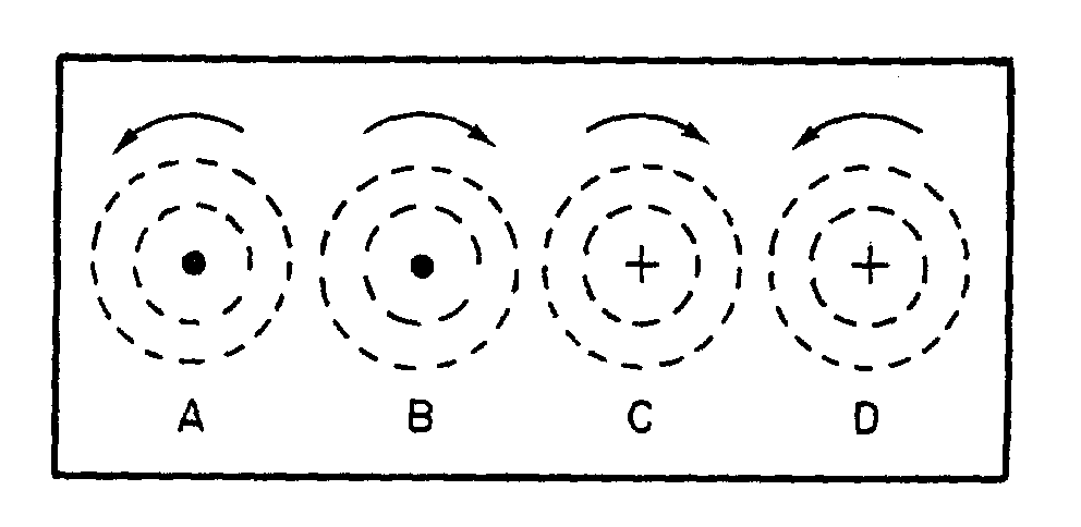
Figure 1A.—Conductors, cross-sectional view.
1
ASSIGNMENT 1
Textbook assignment: Chapter 1, “Concepts of Alternating Current,” pages 1-1 through 1-33. _________________________________________________________________________________
1-1. Alternating current can be defined as current that varies in
1. amplitude and direction 2. magnitude and phase 3. amplitude and time 4. time and phase
1-2. Before a 120-volt dc source can be used to power a 12-volt load, the voltage must be reduced. Which of the following methods can be used?
1. A resistor placed in parallel with the
load 2. A resistor placed in series with the
load 3. A step-down transformer placed in
series with load 4. A step-down transformer placed in
parallel-with the load
1-3. Alternating current has replaced direct current in modern transmission systems because it has which of the following advantages?
1. Ac can be transmitted with no line
loss 2. Ac can be transmitted at higher
current levels 3. Ac can be transmitted at lower
voltage levels 4. Ac can be readily stepped up or
down
1-4. A waveform is a graphic plot of what quantities?
1. Current versus time 2. Amplitude versus time 3. Voltage versus amplitude 4. Magnitude versus amplitude
1-5. Which of the following properties surrounds a current-carrying conductor?
1. A magnetic field 2. A repulsive force 3. An attractive force 4. An electrostatic field
IN ANSWERING QUESTIONS 1-6 AND 1-7, REFER TO FIGURE 1A.
1-6. The direction of the magnetic field is correctly depicted by which of the followings
1. A and B 2. B and D 3. A and C 4. B and C
IN ANSWERING QUESTION 1-7, REFER TO FIGURE 1A AND IGNORE THE MAGNETIC FIELD ARROWS SHOWN IN THE FIGURE.
1-7. In which conductors will the magnetic fields (a) aid, and (b) oppose each other?
1. (a) A and C, (b) C and D 2. (a) A and D, (b) B and C 3. (a) A and C, (b) B and D 4. (a) A and B, (b) A and D
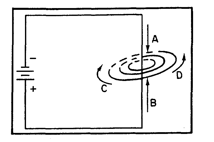
2
Figure 1B.—A magnetic field surrounding a current-
carrying conductor.
IN ANSWERING QUESTIONS 1-8, REFER TO FIGURE 1B.
1-8. In figure 1B, the direction of the magnetic field surrounding the conductor is correctly indicated by what arrow?
1. A 2. B 3. C 4. D
1-9. Which of the following statements
accurately describes the magnetic field surrounding a current-carrying conductor?
1. It is parallel to and equal along all
parts of the conductor 2. It is parallel to and maximum at the
most negative part of the conductor 3. It is perpendicular to and equal
along all parts of the conductor 4. It is perpendicular to the conductor
and maximum at the most negative point of the conductor
1-10. Which of the following factors determine(s) the intensity of a magnetic field surrounding a coil?
1. The amount of current flow through
the coil 2. The type of core material 3. The number of turns in the
conductor 4. All of the above
1-11. When you grasp a coil in your left hand with your thumb pointing in the direction of the north pole, your fingers will be wrapped around the coil in the direction of the
1. voltage potential 2. magnetic field 3. current flow 4. south pole
1-12. The power consumed in a conductor in
realigning the atoms which set up the magnetic field is known as what type of loss?
1. Hysteresis loss 2. Magnetic loss 3. Field loss 4. Heat loss
1-13. The magnetic field surrounding a straight conductor is (a) what shape, and (b) is in what position relative to the conductor?
1. (a) Linked oblong (b) Parallel 2. (a) Concentric circles (b) Parallel 3. (a) Linked oblong (b) Perpendicular 4. (a) Concentric circles (b) Perpendicular
3
1-14. Why is a two-pole magnetic field set up around a coil?
1. Because separate lines of magnetic
force link and combine their effects 2. Because concentric lines of force
cross at right angles and combine. 3. Because lines of force are separated
and bent at the coil ends 4. Because separate lines of force are
attracted to the two poles of the coi
1-15. When a conductor is moving parallel to magnetic lines of force, (a) what relative number of magnetic lines are cut, and (b) what relative value of emf is induced?
1. (a) Minimum, (b) maximum 2. (a) Minimum, (b) minimum 3. (a) Maximum, (b) maximum 4. (a) Maximum, (b) minimum
1-16. When the induced voltage in a conductor rotating in a magnetic field is plotted against the degrees of rotation, the plot will take what shape?
1. A circle 2. A sine curve 3. A square wave 4. A straight line
1-17. When a loop of wire is rotated through 360º in a magnetic field, the induced voltage will be zero at which of the following points?
1. 45º 2. 90º 3. 180º 4. 270º
1-18. When a loop of wire is rotated 360º in a magnetic field, at what points will the induced voltage reach its maximum (a) positive, and (b) negative values?
1. (a) 0º , (b) 180º 2. (a) 0º , (b) 270º 3. (a) 90º , (b) 180º 4. (a) 90º , (b) 270º
1-19. When a coil of wire makes eight complete revolutions through a single magnetic field, (a) what total number of alternations of voltage will be generated and, (b) what total number of cycles of ac will be generated?
1. (a) 32, (b) 16 2. (a) 16, (b) 8 3. (a) 8, (b) 4 4. (a) 4, (b) 2
1-20. According to the left-hand rule for generators, when your thumb points in the direction of rotation, your (a) forefinger and (b) your middle finger will indicate the relative directions of what quantities?
1. (a) Current,
(b) Magnetic flux, south to north 2. (a) Current,
(b) Magnetic flux, north to south 3. (a) Magnetic flux, south to north,
(b) Current 4. (a) Magnetic flux, north to south,
(b) Current
1-21. Continuous rotation of a conductor through magnetic lines of force will produce what type of (a) voltage and (b) waveform?
1. (a) Ac, (b) sine wave 2. (a) Dc, (b) continuous level 3. (a) Ac, (b) sawtooth 4. (a) Dc, (b) pulsating wave
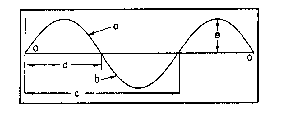
Figure 1C.—Components of a sinewave. _______________________________________ IN ANSWERING QUESTIONS 1-27 THROUGH 1-36, REFER TO FIGURE 1C. IN ANSWERING QUESTIONS 1-27 THROUGH 1-31, SELECT FROM COLUMN B THE COMPONENT THAT IS DESCRIBED BY THE TERM IN COLUMN A.
4
1-22. What is the term for the number of complete cycles of ac produced in one second?
1. Period 2. Waveform 3. Frequency 4. Wavelength
1-23. What is the unit of measurement for frequency?
1. Cycle 2. Hertz 3. Period 4. Maxwell
1-24. A loop of wire rotating at 60 rpm in a magnetic field will produce an ac voltage of what frequency?
1. 1 Hz 2. 60 Hz 3. 120 Hz 4. 360 Hz
1-25. An ac voltage of 250 hertz has a period of
1. 0.004 second 2. 0.025 second 3. 0.4 second 4. 2.5 seconds
1-26. What is the approximate frequency of an
ac voltage that has a period of .0006 second?
1. 6 Hz 2. 16.67 Hz 3. 600 Hz 4. 1667 Hz
A. TERM
B. COMPONENT
1-27. Period 1. a 1-28. Negative
alternation 2. 3.
b c
1-29. Wavelength 4. d 1-30. One-half cycle 1-31 Postive
alternation
_______________________________________
1-32. Component a is a measure of what quantity?
1. Frequency 2. Polarity 3. Amplitude 4. Time
1-33. Component a differs from component b in which of the following characteristics
1. Frequency 2. Polarity 3. Amplitude 4. Period
5
1-34. Component c would represent what quantities if it were expressed as (a) physical distance, and (b) time?
1. (a) Frequency (b) period 2. (a) Period (b) wavelength 3. (a) Frequency (b) wavelength 4 (a) Wavelength (b) period
1-35. The combined values of components a and b represent what ac value?
1. Peak-to-peak value 2. Average value 3. Effective value 4. Instantaneous value
1-36. A peak voltage is represented by which of the following components?
1. a 2. c 3. d 4. e
1-37. An ac voltage has a frequency of 350 Hz. In two seconds, what total number of times will the peak value of voltage be generated?
1. 350 times 2. 700 times 3. 1400 times 4. 2800 times
1-38. The value of current of an ac waveform taken at any particular moment of time is what type of value?
1. Average value 2. Effective value 3. Instantaneous value 4. Peak-to-peak value
1-39. While the value of an ac voltage may be expressed as one of several values, the accepted practice is to express it as what type value?
1. Average value 2. Instantaneous value 3. Peak-to-peak value 4. Effective value
1-40. The total of ten instantaneous values of an alternation divided by ten is equal to what value?
1. The peak value 2. The average value 3. The instantaneous value 4. The effective value
1-41. Which of the following mathematical
formulas is used to find the average value of voltage for an ac voltage?
1. Eavg = 0.707 × Emax 2. Eavg = 1.414 × Eeff 3. Eavg = 0.636 × Emax 4. Eavg = 0.226 × Eeff
1-42. What is the average value of all of the instantaneous voltages occurring during one cycle of an ac waveform with a peak value of 60 volts?
1. 0 volts 2. 38 volts 3. 76 volts 4. 128 volts
1-43. If an ac voltage has an Emax of 220 volts, what is Eavg?
1. 50 volts 2. 140 volts 3. 156 volts 4. 311 volts
6
1-44. If an ac waveform has a peak-to-peak value of 28 volts, what is E avg?
1. 40 volts 2. 20 volts 3. 18 volts 4. 9 volts
1-45. If an ac waveform has a peak value of
4.5 amperes, what is its average value?
1. 2.9 amperes 2. 3.2 amperes 3. 5.7 amperes 4. 6.4 amperes
1-46. If the average value of current of an ac waveform is 1.2 amperes, what is its maximum value of current?
1. 0.8 amperes 2. 0.9 amperes 3. 1.7 amperes 4. 1.9 amperes
1-47. The value of alternating current that will heat a resistor to the same temperature as an equal value of direct current is known as
1. Iavg 2. Ieff 3. Iin 4. Imax
1-48. The rms value for an ac voltage is equal
to what other ac value?
1. Eavg 2. Emax 3. Eeff 4. Ein
1-49. What value will result by squaring all values for Einst, averaging these values, and then taking the square root of that average?
1. Eavg 2. Emax 3. Eeff 4. Ein
1-50. The accepted, nominal value for
household power in the United States is 120-volts, 60 Hz. What is the value of maximum voltage?
1. 170 volts 2. 120 volts 3. 85 volts 4. 76 volts
1-51. An ac voltmeter is usually calibrated to read which of the following ac values?
1. Average 2. Effective 3. Peak 4. Peak-to-peak
1-52. If the maximum value for an ac voltage is known, the Eeff can be found by using which of the following formulas?
1. Eeff = Emax/.636 2. Eeff = Emax/.707 3. Eeff = Emax × .707 4. Eeff = Emax × 1.414
1-53. If the Ieff of an ac waveform is 3.25
amperes, what is Imax?
1. 4.6 amperes 2. 2.3 amperes 3. 2.1 amperes 4. 1.6 amperes
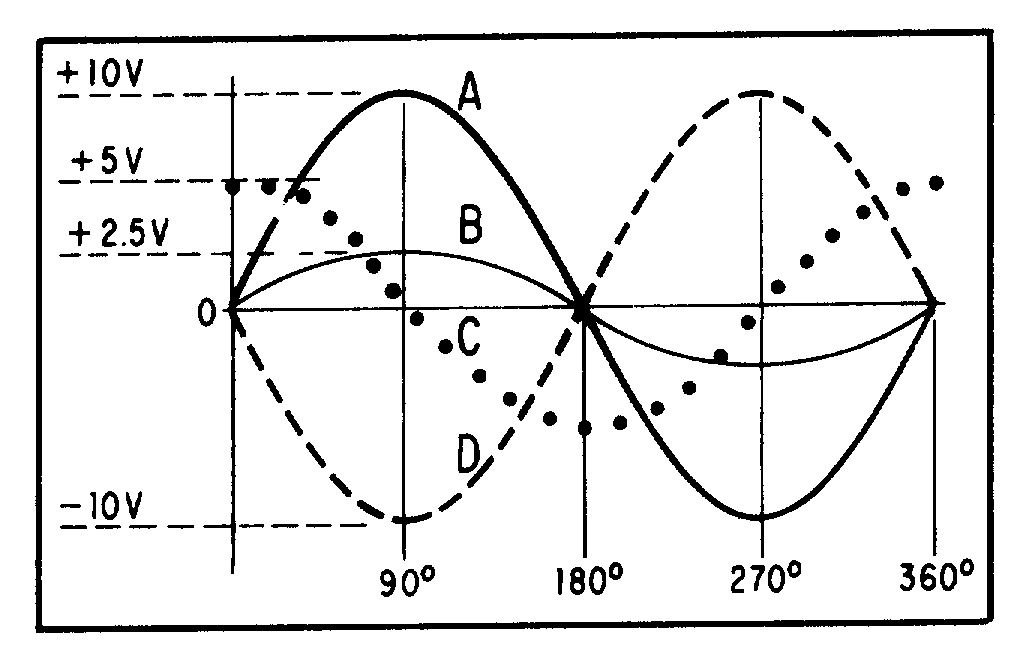
7
1-54. If the rms value of the voltage of an ac waveform is 12.4 volt what is its average value? (Hint: compute Emax first.)
1. 8 volts 2. 11 volts 3. 15 volts 4. 18 volts
Figure 1D.—Phase relationship of sinewaves.
IN ANSWERING QUESTIONS 1-55 THROUGH 1-60, REFER TO FIGURE 1D. 1-55. What two waveforms are in phase?
1. A and B 2. A and C 3. C and D 4. B and C
1-56. What is the phase difference, if any,
between waveform B and C?
1. B is 225º out of phase with C 2. B is 180º out of phase with C 3. B is 90º out of phase with C 4. None; they are in phase
1-57. What is the phase difference, if any, between waveform A and D?
1. A is 270º out of phase with D 2. A is 180º out of phase with D 3. A is 90º out of phase with D 4. None; they are in phase
1-58. If the voltage represented by waveform A is summed to the voltage represented by waveform D, what is the resultant voltage?
1. 20 volts 2. 15 volts 3. 10 volts 4. 0 volts
1-59. What is Ein at 90º that results from adding waveform B to waveform D?
1. +7.5 volts 2. +2.5 volts 3. -7.5 volts 4. -10 volts
1-60. What is the phase difference between
waveform A and waveform C?
1. A lags C by 90º 2. A leads C by 90º 3. A leads C by 180º 4. A lags C by 180º
1-61. Which of the following is an important rule to remember when using Ohm's Law to solve ac circuit problems?
1. Always solve for resistance first 2. Give the answer as effective value 3. Never mix values 4. Convert all given values to effective
before attempting to solve
1-62. An ac circuit is composed of three 20- ohm resistors connected in parallel. The average voltage supplied to this circuit is 62-volts ac. What is the maximum current?
1. 9.3 amperes 2. 14.6 amperes 3. 17.5 amperes 4. 22.5 amperes
8
1-63. If the ac source in question 1-62 is raised to an average value of 120 volts, what is the Ieff?
1. 11.48 amperes 2. 12.70 amperes 3. 20.01 amperes 4. 25.52 amperes
1-64. If Eeff is 150 volts and Imax is 4.5 amperes, what is the total resistance (RT) of a circuit?
1. 21.2Ω 2. 23.6Ω 3. 33.3Ω 4. 47.1Ω
9
ASSIGNMENT 2 Textbook assignment: Chapter 2, “Inductance,” pages 2-1 through 2-27.
_________________________________________________________________________________
2-1. The property of inductance offers opposition to which of the following quantities?
1. Constant current 2. Constant voltage 3. Changes in current 4. Changes in voltage
2-2. What is the symbol for inductance?
1. L 2. H 3. XL 4. IND
2-3. What is the unit of measurement for inductance?
1. Ohm 2. Rel 3. Farad 4. Henry
2-4. If 9 volts are induced in a conductor when the current changes by 4.5 amperes in one second, what is the total inductance of the circuit?
1. 1.5 henries 2. 2.0 henries 3. 13.5 henries 4. 40.0 henries
2-5. What physical property is similar to inductance?
1. Mass 2. Motion 3. Velocity 4. Inertia
2-6. The difference in potential across a resistor, created by current through the resistor is an example of which of the following forces?
1. Resistive 2. Inertia 3. Inductive 4. Electromotive
2-7. When a magnetic field moves through a stationary conductor, the electrons in orbit are affected in what manner?
1. They are dislodged from orbit 2. They move closer to their nucleus 3. They move closer to other orbiting
electrons 4. They bunch up on one side of the
nucleus
2-8. When electrons are moved in a conductor by a magnetic field, a force known by which of the following terms is created?
1. Voltage 2. Electromotive 3. Potential difference 4. All of the above
2-9. Self-induced emf is also known as what force?
1. magnetic force 2. Inertial force 3. Electromotive force 4. Counter electromotive force
10
2-10. According to Lenz’s Law, the induced emf produced by a change in current in an inductive circuit tends to have what effect on the current?
1. It aids a rise in current and opposes fall in current
2. It aids a fall in current and opposes a rise in current
3. It opposes either a rise or a fall in current
4. It aids either a rise or fall in current
2-11. The direction of the induced voltage in an inductor may be found by application of which of the following rules?
1. The left-hand rule for inductors 2. The left-hand rule for generators 3. The right-hand rule for conductors 4. The right-hand rule for motors
2-12. The left-hand rule for generators states that the thumb of the left hand points in the direction of motion of the
1. conductor 2. magnetic field 3. generator poles 4. induced current
2-13. When source voltage is removed from a current-carrying conductor, a voltage will be induced in the conductor by which of the following actions?
1. The decreasing voltage 2. The collapsing magnetic field 3. The reversal of current 4. The reversing electrical field
2-14. The property of inductance is present in which of the following electrical circuits?
1. An ac circuit 2. A dc circuit 3. A resistive circuit 4. Each of the above
2-15. How are inductors classified?
1. By core type 2. By conductor type 3. By the number of turns 4. By the direction of the windings on
the core
2-16. Normally, most coils have cores composed of either air or
1. copper 2. carbon 3. soft iron 4. carbon steel
2-17. The hollow form of nonmagnetic material found in the center of an air- core coil has what purpose?
1. To focus the magnetic flux 2. To support the windings 3. To act as a low resistance path for
flux 4. To serve as a container for the core
2-18. Which of the following factors will NOT affect the value of inductance of a coil?
1. Number of coil turns 2. Diameter of the coil 3. Conductor tensility 4. Core materials used
2-19. When the number of turns is increased in a coil from 2 to 4, the total inductance will increase by a factor of
1. eight 2. two 3. six 4. four
11
2-20. Why do large diameter coils have greater inductance than smaller diameter coils, all other factors being the same?
1. Large diameter coils have more wire and thus more flux
2. Large diameter coils have less resistance
3. Small diameter coils have less resistance
4. Small diameter coils have large cemfs which oppose current flow
2-21. If the radius of a coil is doubled, its inductance is increased by what factor?
1. One 2. Two 3. Eight 4. Four
2-22. If the length of a coil is doubled while the number of turns is kept the same, this will have (a) what effect on inductance and (b) by what factor?
1. (a) Decrease, (b) by 1/4 2. (a) Decrease, (b) by 1/2 3. (a) Increase, (b) by 2 times 4. (a) Increase, (b) by 4 times
2-23. A soft iron core will increase inductance because it has which of the following characteristics?
1. Low permeability and low reluctance
2. Low permeability and high reluctance
3. High permeability and high reluctance
4. High permeability and low reluctance
2-24. An increase in the permeability of the core of a coil will increase which of the following coil characteristics?
1. Magnetic flux 2. Reluctance 3. Resistance 4. Conductance
2-25. If a coil is wound in layers, its inductance will be greater than that of a similar single-layer coil because of a higher
1. permeability 2. flux linkage 3. reluctance 4. conductance
2-26. Regardless of the method used, inductance of a coil can ONLY be increased by increasing what coil characteristic?
1. Transconductance 2. Reluctance 3. Flux linkage 4. Conductance
2-27. What is the symbol used to denote the basic unit of measurement for inductance?
1. L 2. H 3. I 4. F
2-28. What does the Greek letter Delta signify as in "∆I" or "∆t"?
1. The values are constant 2. The values are average 3. The values are changing 4. The values are effective
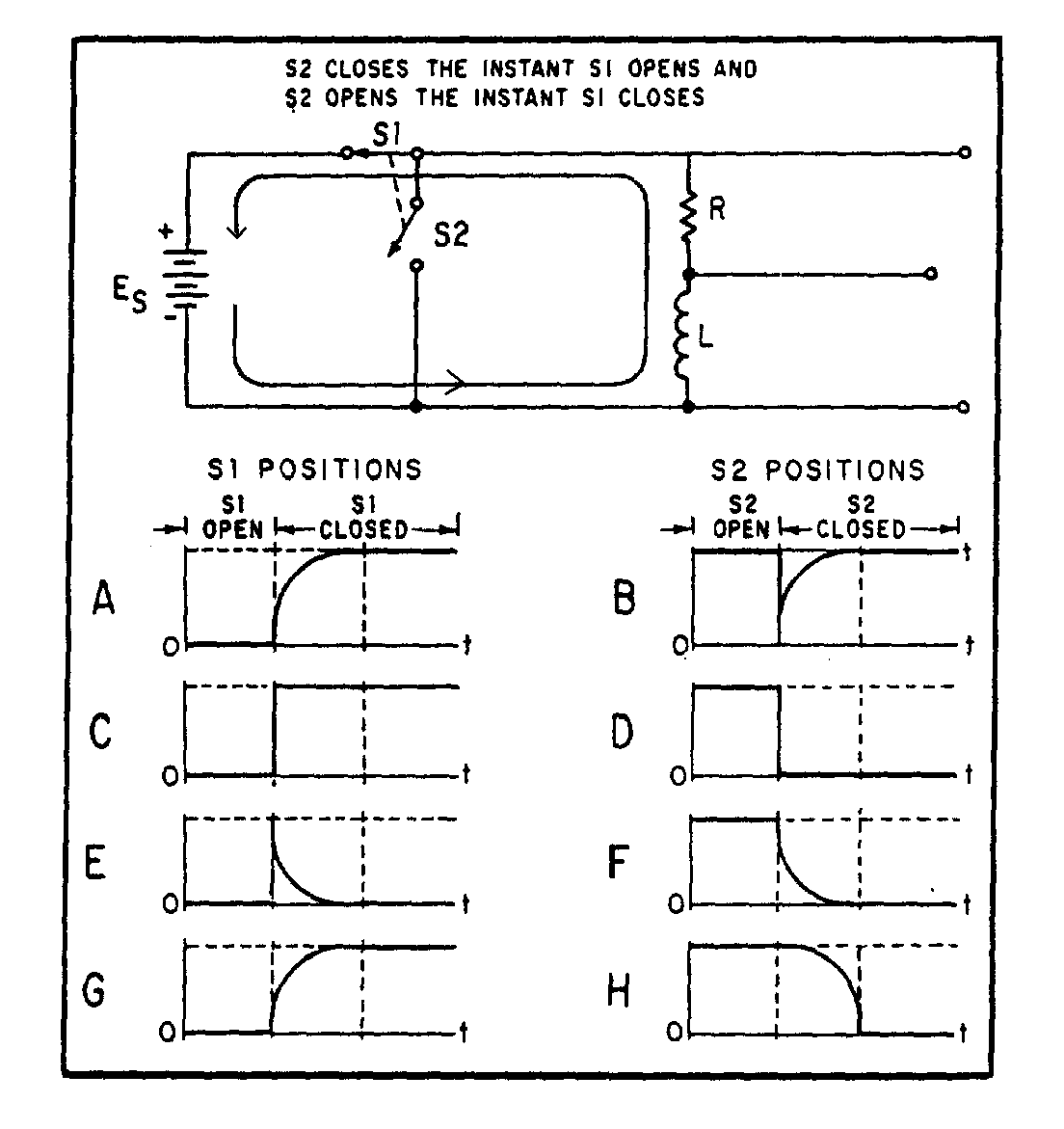
Figure 2A.—LR circuit characteristics.
12
2-29. An electrical circuit contains a coil. When the current varies 2.5 amperes in one second, 7.5 volts are induced in the coil. What is the value of inductance of the coil?
1. 1 henry 2. 2.2 henries 3. 3.3 henries 4. 4 henries
2-30. An ac electrical current varies 1.5 amperes in one second and is applied to a 10-henry coil. What is the value of the emf induced across the coil?
1. 1.0 volt 2. 1.5 volts 3. 11.5 volts 4. 15.0 volts
2-31. If a coil is rated at 10 henries, what is its value in (a) millihenries and (b) microhenries?
1. (a) 10,000 mH, (b) 10,000,000 µH 2. (a) 10,000 mH, (b) 1,000,000 µH 3. (a) 1,000 mH, (b) 1,000,000 µH 4. (a) 1,000 mH, (b) 100,000 µH
THIS SPACE LEFT BLANK INTENTIONALLY.
IN ANSWERING QUESTIONS 2-32 THROUGH 2-40, REFER TO FIGURE 2A.
2-32. What waveform is an illustration of the voltage (ES) present across the voltage divider when switch S1 is closed?
1. B 2. C 3. E 4. G
2-33. The voltage dropped across R when switch S1 is closed is depicted in which of the following waveforms?
1. G 2. H 3. F 4. C
13
2-34. The voltage developed across L when switch S1 is closed is depicted in what waveform?
1. A 2. B 3. E 4. H
2-35. Which of the following waveforms depicts growth current (I
g) through the coil (L)?
1. A 2. D 3. E 4. H
2-36. What waveform depicts the voltage developed across R when switch S2 is closed?
1. E 2. F 3. H 4. D
2-37. During the first instant when switch S1 is closed, maximum voltage is dropped across
1. the battery 2. the resistor 3. the coil 4. both the coil and resistor
2-38. During the first instant when switch S1 is closed, current is maximum in which, if any, of the following parts of the h circuit?
1. The battery 2. The coil 3. The resistor 4. None of the above
2-39. In the first instant when switch S1 is closed, the entire battery-voltage is used to overcome the
1. resistance of R 2. resistance of L 3. emf developed in R 4. emf developed in L
2-40. When switch S2 is closed, energy is supplied to the circuit by the
1. battery through S2 2. battery through S1 3. collapsing magnetic field of L1 4. expanding magnetic field of L1
2-41. One L/R time constant is equal to the time required for the current in an inductor to reach what portion of its maximum value?
1. 63.2% 2. 37.8% 3. 25.2% 4. 12.8%
2-42. Maximum current will flow in an LR circuit after a minimum of how many time constants have elapsed?
1. One 2. Five 3. Three 4. Four
2-43. The maximum current in an LR circuit is 20 amperes. What total current will be flowing in the circuit at the end of the second time constant of the charge cycle?
1. 20.0 amperes 2. 17.3 amperes 3. 12.6 amperes 4. amperes


14
2-44. Refer to the circuit described in question 2-43. Circuit current will increase by what amount during the second time constant?
1. 17.3 amperes 2. 12.6 amperes 3. 7.6 amperes 4. 4.7 amperes
2-45. An LR circuit has a maximum current of 30 mA. At the end of the first time constant of the discharge cycle, what total current will be flowing in the circuit?
1. 11 mA 2. 19 mA 3. 26 mA 4. 28 mA
2-46. An LR circuit contains a 150-ohm resistor and a 2-henry coil. What is the time value of one L/R time constant?
1. 7.5 seconds 2. .75 seconds 3. 1.33 seconds 4. .0133 seconds
2-47. An LR circuit has a time constant of .05 second and an inductor with a value of .60 henry. What value of resistor is required?
1. 5 ohms 2. 12 ohms 3. 24 ohms 4. 64 ohms
2-48. An LR circuit is composed of a coil of .5 henry and a 10-ohm resistor. The maximum current in the circuit is 5 amperes. After the circuit is energized, how long will it take for the current to reach maximum value?
1. 1.0 second 2. 0.05 second 3. 0.25 second 4. 5.0 seconds
2-49. Inductors experience copper loss for what reason?
1. Because of flux leakage in the copper core
2. Because the reactance of an inductor is greater than the resistance of an inductor
3. Because all inductors have resistance which dissipates power
4. Because the inertia of the magnetic field must be overcome every time the direction of current changes
2-50. Copper loss of an inductor can be calculated by the use of which of the following formulas?
1. 3.
2. 4.
2-51. What term applies to the power loss in an iron core inductor due to the current induced in the core?
1. Iron loss 2. Heat loss 3. Hysteresis loss 4. Eddy-current loss
2-52. Power consumed by an iron core inductor in reversing the magnetic field of the core is termed as what type of loss?
1. Iron loss 2. Heat loss 3. Hysteresis loss 4. Eddy-current loss
15
2-53. When does mutual inductance occur between inductors?
1. Whenever eddy-currents do not exist
2. Whenever the flux of one inductor causes an emf to be induced in another inductor
3. Whenever the effect of one inductor is aided by another inductor
4. Whenever the effect of one inductor is opposed by another inductor
2-54. Mutual inductance between two coils is affected by which of the following factors?
1. Material of the windings 2. Physical dimensions of the coils 3. Direction of the coil windings 4. Hysteresis characteristics of the
coils
2-55. The coefficient of coupling between two coils is a measure of what factor?
1. The turns ratio of the coils 2. The distance between the coils 3. The relative positive of the coils 4. The magnetic flux ratio linking the
coils
2-56. Two coils have a coefficient of coupling of .7 and are rated at 12 µH and 3 µH respectively. What is their total mutual inductance?
1. 4.2 µH 2. 5.2 µH 3. 7.0 µH 4. 10.5 µH
2-57. An electrical circuit contains four non- coupled inductors in a series configuration. The inductors have the following values: 2 µH, 3.5 µH, 6 µH, and 1 µH. What is the total inductance (LT) of the circuit?
1. 45.0 µH 2. 42.5 µH 3. 12.5 µH 4. 11.5 µH
2-58. Two inductors of 3.6 µH and 7.3 µH are wired together in series and they aid each other. The mutual inductance for the circuit is 3.6µH. What is the total inductance (LT) Of the circuit?
1. 17.5 µH 2. 18.1 µH 3. 24.8 µH 4. 34.4 µH
2-59. An electrical circuit contains three non- coupled inductors of 3.3 µH, 4.5 µH, and 2.0 µH wired in parallel. What is the total inductance of the circuit?
1. 9.8 µH 2. 3.6 µH 3. 0.98 µH 4. 0.28 µH
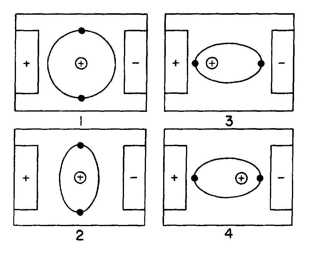
16
ASSIGNMENT 3
Textbook assignment: Chapter 3, “Capacitance,” pages 3-1 through 3-41. _________________________________________________________________________________
3-1. Capacitance and inductance in a circuit are similar in which of the following ways?
1. Both oppose current 2. Both aid voltage 3. Both cause the storage of energy 4. Both prevent the storage of energy
3-2. Capacitance is defined as the property of a circuit that
1. opposes a change in voltage 2. aids a change in voltage 3. opposes a change in current 4. aids a change in current
3-3. A capacitor is a device that stores energy in a/an
1. electrostatic field 2. electromagnetic field 3. induced field 4. molecular field
3-4. Electrostatic fields have what effect on
(a) free electrons, and (b) bound electrons?
1. (a) Attracts them to the negative
charges (b) Frees them from their orbits 2. (a) Attracts them to the positive
charges (b) Frees them from their orbits 3. (a) Attracts them to the negative
charges (b) Distorts their orbits 4. (a) Attracts them to the positive
charges (b) Distorts their orbits
3-5. The influence of a charge on an electron
orbit is correctly depicted by which of the following illustrations?
3-6. Electrostatic lines of force radiate from
a charged particle along what type of lines?
1. Straight lines 2. Curved lines 3. Elliptical lines 4. Orbital lines
THIS SPACE LEFT BLANK INTENTIONALLY.
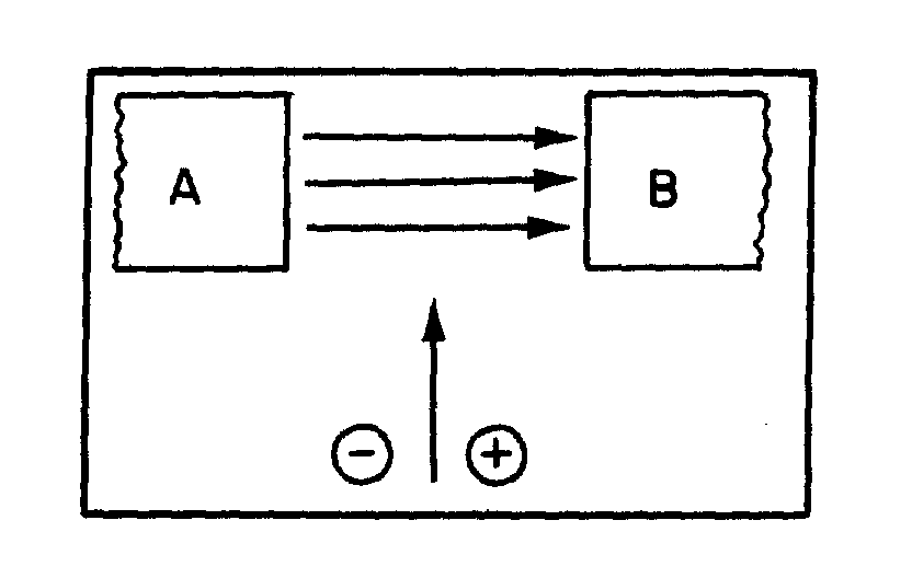
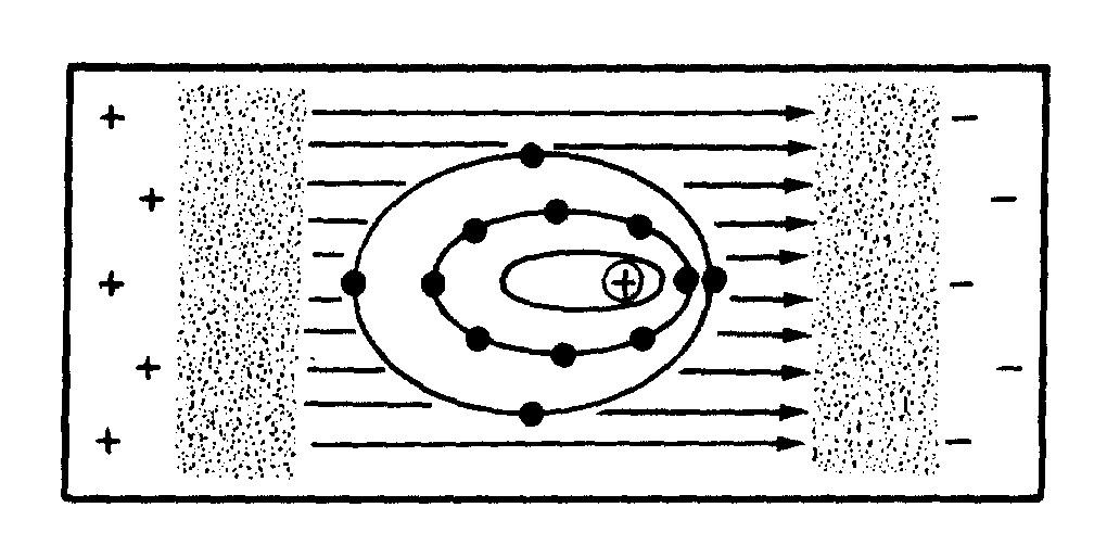
17
Figure 3A.—Electron and proton entering an
electrostatic field.
IN ANSWERING QUESTION 3-7, REFER TO FIGURE 3A.
3-7. When the illustrated electron and proton enter the electrostatic field, toward what plate(s), will the (a) electron and, (b) proton be deflected?
1. (a) A (b) B 2. (a) B (b) A 3. (a) A (b) A 4. (a) B (b) B
Figure 3B.—Effect of electrostatic lines of force.
IN ANSWERING QUESTION 3-8, REFER TO FIGURE 3B.
3-8. If the charges on the two plates are reversed, what will happen to the electrons?
1. They will dislodge from the atom 2. They will stay where they are 3. They will go back to circular orbits 4. They will distort in the opposite
direction
3-9. Which of the following combinations describe(s) a simple capacitor?
1. Two copper plates separated by an
iron plate 2. Two copper plates separated by a
sheet of mica 3. Two iron plates separated by an air
gap 4. Both 2 and 3 above
3-10. A capacitor that stores 6 coulombs of
electrons when a potential of 2 volts is applied across its terminals has what total value of capacitance?
1. 12 farads 2. 8 farads 3. 3 farads 4. 6 farads
___________________________________
IN ANSWERING QUESTIONS 3-11 THROUGH 3-14, MATCH THE TERMS IN COLUMN B WITH THEIR MATHEMATICAL VALUES IN COLUMN A. A. VALUES
B. TERMS
3-11. .000001 F 1. Farad 3-12. 1 x 10-12 F 2. Microfarad 3-13. 1 x 10⁻⁶ F 3. Picofarad 3-14. 1 x 100 F
___________________________________
3-15. A capacitor of .0069 microfarad has which of the following capacitance values when measured in picofarads?
1. .000069 pF 2. 6900 pF 3. 6.9 × 10⁻⁹ pF 4. Both 2 and 3 above, individually,
are correct
18
3-16. Which of the following characteristics of a capacitor can be varied WITHOUT altering its capacitance?
1. Area of the plates 2. Thickness of the dielectric 3. Material of the dielectric 4. Thickness of the plates
3-17. Which of the following actions will increase the capacitance of a capacitor?
1. The plates are moved closer
together 2. The plates are moved farther apart 3. The dielectric constant is decreased 4. Both 2 and 3 above
3-18. Two capacitors are identical with the exception of the material used for the dielectric. Which of the following combinations of dielectric material will cause capacitor (b) to have a larger capacitance than capacitor (a)?
1. (a) Glass (b) Paraffin paper 2. (a) Glycerine (b) Pure water 3. (a) Petroleum (b) Air 4. (a) Paraffin paper (b) Petroleum
3-19. Two capacitors are identical with the exception of the material used for the dielectric. Which of the following combinations of dielectric materials will cause the capacitors to have almost the same capacitance?
1. Glass, paraffin paper 2. Mica, petroleum 3. Vacuum, air 4. Petroleum, rubber
3-20. A capacitor is composed of two plates. Each plate has an area of 7 square inches. The plates are separated by a 2- inch thick paraffin paper dielectric. What is its capacitance?
1. 2.76 µF 2. 2.76 pF 3. 5.51 µF 4. 5.51 pF
3-21. The maximum voltage that can be applied to a capacitor without causing current flow through the dielectric is called
1. breaking voltage 2. limiting voltage 3. conduction voltage 4. working voltage
3-22. A capacitor with a working voltage of 300 volts would normally have what maximum effective voltage applied to it?
1. 200 volts 2. 250 volts 3. 300 volts 4. 350 volts
3-23. An ac voltage of 350 volts effective can be safely applied to a capacitor with which of the following working voltages?
1. 550 volts 2. 400 volts 3. 350 volts 4. 250 volts
3-24. Which, if any, of the following conditions may cause a capacitor to suffer power losses?
1. Dielectric hysteresis 2. Plate loading 3. Plate heating 4. None of the above
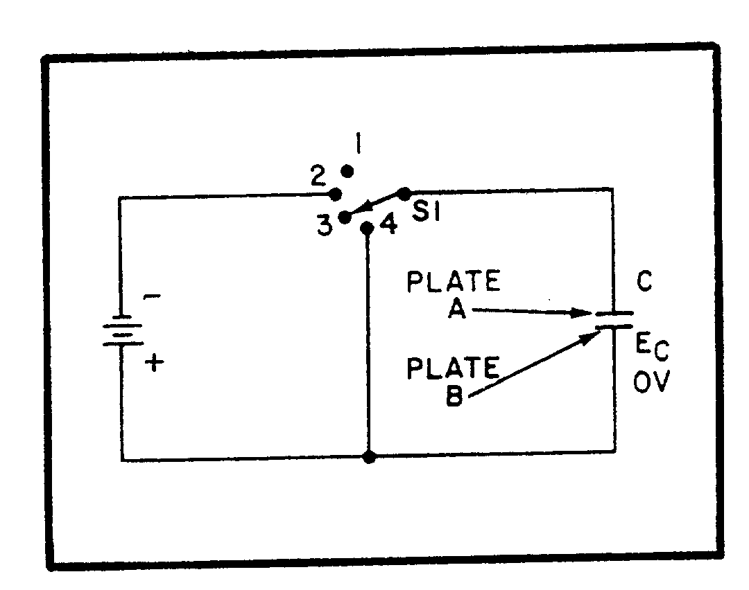
19
3-25. Rapid reversals in the polarity of the line voltage applied to a capacitor will cause what type of capacitor power loss?
1. Dielectric-leakage 2. Dielectric-hysteresis 3. Plate-loading 4. Plate-leakage
3-26. What type of dielectric is LEAST sensitive to power dielectric-hysteresis losses?
1. Pure water 2. Air 3. Vacuum 4. Mica
3-27. As the current through a capacitor increases, which of the following types of capacitor losses will increase?
1. Dielectric-hysteresis 2. Dielectric-leakage 3. Plate-leakage 4. Plate-breakdown
Figure 3C.—Simple capacitor circuit.
IN ANSWERING QUESTIONS 3-28 THROUGH 3-33, REFER TO FIGURE 3C.
3-28. Assume that the switch has been moved from position 4 to the position shown. Which of the following conditions now exists?
1. An electrostatic field exists between
the capacitor's plates 2. No potential difference exists across
the capacitor 3. Current flow is at its maximum 4. Energy is being stored in the
capacitor's electrostatic field
3-29. To charge the capacitor, the switch must be in what position?
1. 1 2. 2 3. 3 4. 4
3-30. Which of the following are paths for
current flow when the capacitor is charging? 1. Plate A, Plate B, Batt (+) and -Batt (−),
Plate A 2. Batt (+) and -Batt (−), Plate A
Batt (−) and Batt (+), Plate B 3. Batt (−), Plate A and Plate B,
Batt (+), Batt (−) 4. Batt (+), Plate B and Plate A,
Batt (−), Batt (+)
3-31. When the switch is placed in position 4, after being in position 2, which of the following conditions exits within the circuit?
1. EC is increasing 2. LC is increasing 3. Electrical energy is stored in the
capacitor 4. Stored energy is returned to the
circuit
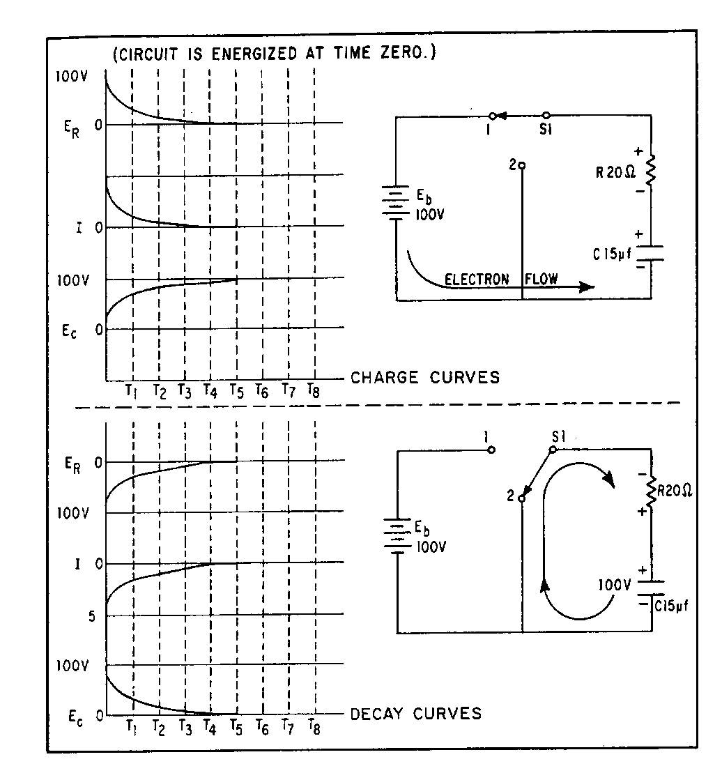
Figure 3D.—RC charge and discharge circuits.
20
3-32. With S1 in position 4, which of the following is the path for current flow?
1. Plate B, Plate A, S1, Plate B 2. Plate A, Plate B, S1, Plate A 3. Plate A, S1, Plate B 4. Plate B, S1, Plate A
3-33. If the illustrated capacitor has a value of
50 pF and a potential difference of 300 volts exists across its plates, what is the total number of coulombs it contains?
1. 0.015 2. 0.15 3. 1.50 4. 15.0
IN ANSWERING QUESTIONS 3-34 THROUGH 3-41, REFER TO FIGURE 3D.
3-34. The greatest rate of change in current occurs between what two times?
1. T1 − T2 2. T2 − T3 3. T4 − T5 4. T0 − T1
3-35. At what instant does the maximum voltage appear across the resistor?
1. T1 2. T2 3. T5 4. T0
3-36. When the charge on the capacitor is equal to 100 volts, what is the voltage drop across the resistor?
1. 100 volts 2. 63 volts 3. 27 volts 4. 0 volts
3-37. After the capacitor has reached full charge, S1 is placed in position 2. The greatest rate of change in current is between what two times?
1. T1 − T2 2. T2 − T3 3. T4 − T5 4. T0 − T1
3-38. The capacitor will be completely discharged at what minimum time interval?
1. T1 2. T5 3. T3 4. T4
Figure 3E.—Universal time constant chart for RC and RL circuit.
21
3-39. What is the RC time constant for the circuit?
1. 300 sec 2. 35 sec 3. 300 µsec 4. 35 µsec
3-40. What total time will it take the capacitor to charge to 98 volts? (You may use figure 3-11 of your text, or figure 3 located on this page.)
1. 140 µsec 2. 1200 µsec 3. 140 sec 4. 1200 sec
3-41. After the capacitor has reached full charge, S1 is moved to position 2. What total number of RC time constants will it take for the capacitor to discharge to 5 volts?
1. One 2. Two 3. Three 4. Four
IN ANSWERING QUESTION 3-42, REFER TO FIGURE 3E ABOVE.
3-42. An RC circuit is designed in which a capacitor must charge to 55 percent (.55) of the maximum charging voltage in 200 microseconds. The resistor has a value of 30,000 ohms. What value of capacitance is needed?
1. 0.0089 pF 2. 89.0 pF 3. 0.0089 µF 4. 89.0 µF
_______________________________________
MATCH THE CAPACITOR CONFIGURATION IN COLUMN B WITH THE CHARACTERISTICS IN COLUMN A.
A. CHARACTERISTICS
B. CONFIGURATION
3-43. Increases total capacitance
1. Capacitors in parallel
3-44. Effectively moves plates further apart
2. Capacitors in series
3-45. Increases plate area 3-46. Total capacitance is found
by adding all capacitances
3-47. Decreases total capacitance
3-48. Similar to resistors in parallel
_______________________________________
3-49. A circuit contains four parallel- connected capacitors of 33 µF each. What is the total capacitance of the circuit?
1. 8.3 µF 2. 33.0 µF 3. 183.0 µF 4. 132.0 µF
3-50. A circuit contains two series-connected capacitors of 15 µF, and 1500 pF. What is the total capacitance of the circuit?
1. 0.0015 pF 2. 150.0 pF 3. 0.0015 µF 4. 0.1500 µF
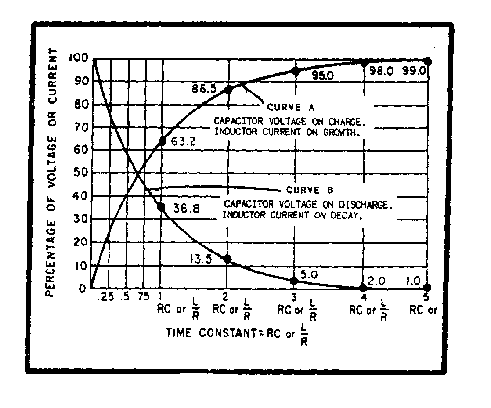
22
3-51. A circuit contains two 10 µF capacitors wired together in a parallel configuration. The two parallel-wired capacitors are wired in series with a 20 µF capacitor and a 20 K ohm resistor. Which of the following expresses the RC time constant for this circuit?
1. .2 sec 2. 2 sec 3. 20,000 sec 4. Both 2 and 3 above
3-52. How are fixed capacitors classified?
1. By their plate size 2. By their dielectric materials 3. By the thickness of their dielectric
materials 4. By the thickness of their conductors
3-53. Which of the following types of capacitors are referred to as self- healing?
1. Ceramic 2. Paper 3. Oil 4. Mica
_______________________________________
MATCH THE CAPACITOR TYPE IN COLUMN B WITH THE CHARACTERISTIC IN COLUMN A. A. CHARACTERISTIC
B. TYPE
3-54. Has an oxide film dielectric
1. Electrolytic
3-55. Can be adjusted by a screw setting
2. Trimmer
3-56. A polarized capacitor 3. Mica 3-57. Has a waxed paper
dielectric 4. Paper
3-58. An adjustable capacitor with a mica dielectric
_______________________________________
Figure 3F.—Types of capacitors.
IN ANSWERING QUESTIONS 3-59 THROUGH 3-63, REFER TO FIGURE 3F AND TO THE ASSOCIATED PAGES IN YOUR TEXTBOOK. 3-59. Capacitor A is what type of capacitor?
1. Electrolytic 2. Ceramic 3. Paper 4. Mica
3-60. Capacitor B is what type of capacitor?
1. Mica 2. Paper 3. Ceramic 4. Electrolytic
3-61. What is the capacitance of capacitor B?
1. 2,200,000 pF 2. 2,200,000 µF 3. 72,000 pF 4. 72,000 µF
23
3-62. What is the (a) temperature coefficient and (b) multiplier of capacitor C?
1. (a) -30 (b) 100 2. (a) -30 (b) 1000 3. (a) -330 (b) 100 4. (a) -330 (b) 1000
3-63. What is the (a) capacitance, and (b) voltage rating of capacitor D? 1. (a) 4800 µF (b) 200 volts 2. (a) 4800 pF (b) 200 volts 3. (a) 98,000 µF (b) 800 volts 4. (a) 980,000 pF (b) 800 volts
�
� �
ASSIGNMENT 4 �
-�5����'���� �� �����&������� $�O2����� �������&���� � ���0��������$P������� ����������� � 7���&�������
!$�O-������� ���$P�������!�����������!�����
QQQQQQQQQQQQQQQQQQQQQQQQQQQQQQQQQQQQQQQQQQQQQQQQQQQQQQQQQQQQQQQQQQQQQQQQQQQQQQQQQQQQQ�
�
���� 2�������������������������$� �����$������
������� ��*�+��������$�����*�+��� ����I�
�
��� *�+�1������������ *�+�� ��� ��
��� *�+�) ��� �������� *�+�����������
��� *�+�:������� �� *�+�����������
�� *�+�1��������� *�+��������� ��
�
���� =� ����� ������������� ���� ����������
�� �� ������������� ��� ��I�
�
��� 0�� �� ���
��� &���� � ���
��� 8������������������
�� 2����� ���
�
���� :���� � ����������� �������������������
�� � ��������� ��� �� �����������������
������� �� I�
�
��� 0�
��� B.�
��� .�
�� ,�
�
� �� 6���� ����������� � ������������������ �
���*�+������ ������� ������ ���������������
*�+���������� ���������I�
�
��� *�+�0�� ������� *�+�2����������
��� *�+�0���������� *�+�&����������������
��� *�+�0��������� *�+�2����������
�� *�+�0�� ������� *�+�0���������
�
�!�� -������ � ���π�.� ��������������� ��� ������ ���� �� �#���� ��I�
�
��� 0�� �������
��� 2����������
��� &����������� ���
�� 2����� �������������
�
�"�� )�� ����� ���� ��� ������� ������77�R,�
�� �������������� �������� ��� �������
���#�����������7�,@��6���� �������� ���
���������������������� ��� �I�
�
��� ��7��!�� ��� ����!7�� ��� ��%�!7�� �� %!�7�� �
�%�� 2���������#��������� ��������� ��� ��� ���
���77�R,��� � �� ������������ ���7�,@�
���!7�',@$������� ���������� ������
������������������� ��� �I�
�
��� ������7�%!�� ��� ������%�!�� ��� ������"��(�� �� "�(�7�� �
�(�� )������ ����� �*�+�������������������
����������$�����*�+�� ��'��������������
�������I�
�
��� *�+�<�� *�+�) ����
��� *�+�) ���� *�+�<��
��� *�+�<�� *�+�)��������"7�,@�
�� *�+�)��������"7�,@� *�+�<��
�
�
�
-,2���G)&/�./9-�8.)1J�
21-/1-2:1)..4��
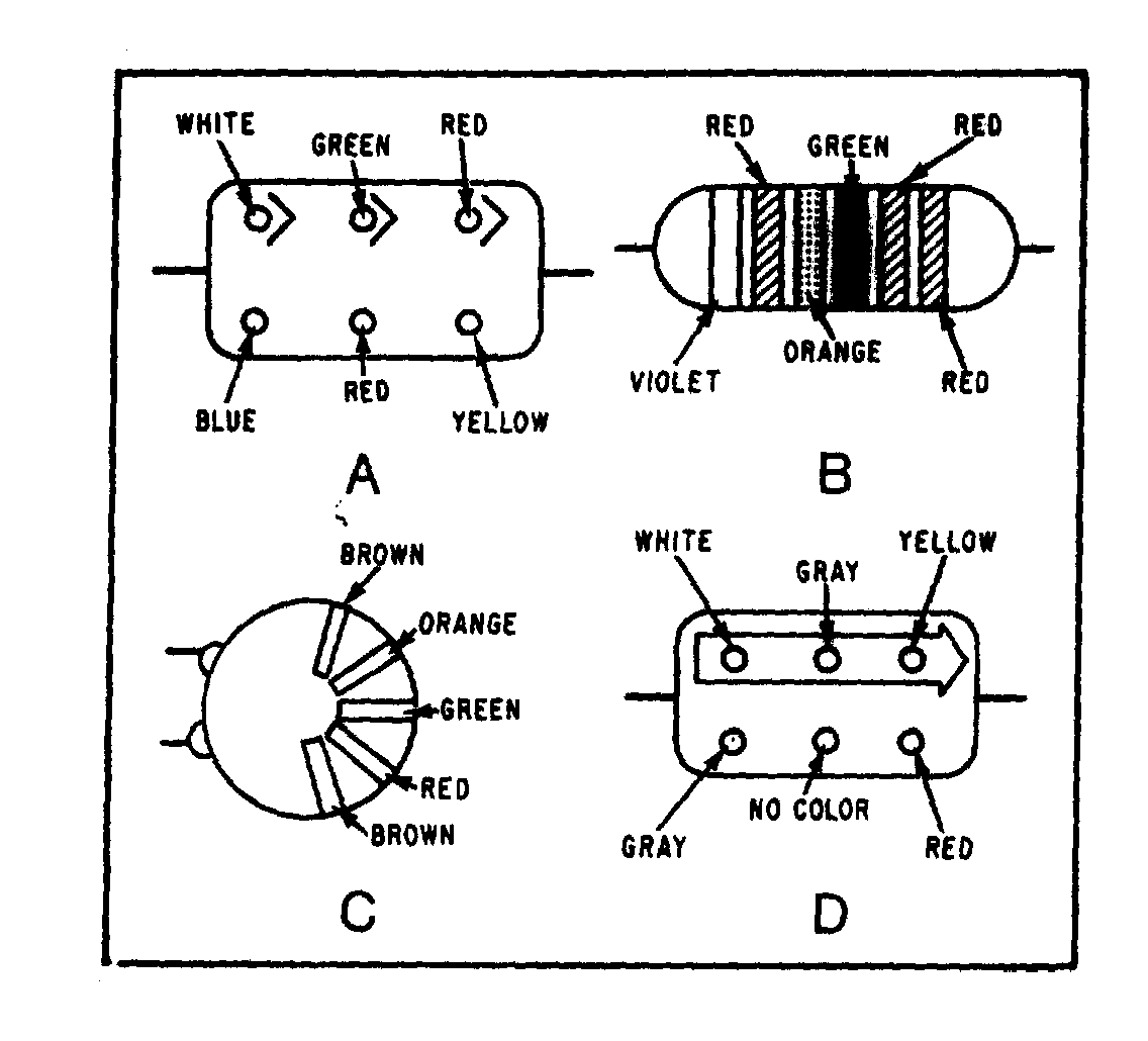

�
�!�
21�)1�6/0213�H�/�-2:1�� �?�
-,0:�3,� ���$��/./&-�90:;�&:.�;1�
8�-,/�G0:G/0-4�-,)-�&)��/��-,/�
/./&-02&).�/99/&-�21�&:.�;1�)��
�
�� �?�� :���� � ���������
�����������
��� 2����� ���
����������
��7�� &��������������
�� �������������
�� ���������
��������
��� &���� � ���
����������
����� 2���������� ������
�������� ��
���#������
��� 8������������
������
����� &�����������������
������ �����������
?7E�
�� 0�� �������
����� <���������� ������
�������� ��
���#�������
� �
QQQQQQQQQQQQQQQQQQQQQQQQQQQQQQQQQQQQQQQ�
�
�� �� )��� ���� �� �� ��� ������� ������!�R9�
����� �������������������� ���"7�,@����
��������6���� �������� ����������� � ���
������������������ ��� �I�
�
��� ����7�77�7"�� ��� ����7�7�7"�� ��� ���7�"�� �� �7"����
�
�
-,2���G)&/�./9-�8.)1J�
21-/1-2:1)..4�
21�)1�6/0213�H�/�-2:1�� ��!�)1<�����
��"���/�-,/�9:..:6213�
219:0;)-2:1��)��/02/��&20&�2-�,)��
)1�21<�&-2=/�0/)&-)1&/�:9�!"Ω$�)� &)G)&2-2=/�0/)&-)1&/�:9��!Ω$�)1<� :G/0)-/��)-�)�90/H�/1&4�:9� 77�,F��
�
��!�� 6������� � ������ �������������
����� ����������� �������������������
� ��� �I�
�
��� �
���
�
��� �
�� �
�
��"�� 6���� ���������� ��� ��������������������
����� ��� �I�
�
��� ����������� ��� �������(��� ��� ���$ 77�� �� � $7"%�� �
��%�� 6������� � �����������5�������������� �
����� � ��������� ������ ���� �� �� ��� �I�
�
��� 0���������
��� 2 ��������
��� 0�� �������
�� &�����������
�
��(�� )���� ������� ��� ������������ �� ���
�� �����B.�K�!Ω$�B&�K�"Ω$�����0�K�%Ω�� 6���� �������� ������FI�
�
��� � ��� ����7��� ��� ��%�7%�� �� � �� �� �
�
�"�
��?�� )���� ���� ��� ������� ������ ��������
��� �������� �������� ������������7�
�� ����� ����� ������������� ����� ���
� ���������� ������� �������� �����
����� � ��������������-������ ���
�� ����� ���77��� ����6���� �������� ������
����������������� ��� �I�
�
��� ��"�"�� ���
��� ��(� �� ���
��� �!�7�� ���
�� �!�"�� ���
�
��7�� )���� ���� ��� ������� ������ ��������
��� �������� �������� �����������" �
�� ����� ����� ������������� ����� ���
� ���������� ������� ���"?��� �����
����� � ��������������2��������������
������������� ��� �� ��"�!�� �����$������
�������� ������������ �������� ����������
� ��� �I�
�
��� �"�!��� ���
��� !!�!��� ���
��� %!�!��� ���
�� ( �!��� ���
�
����� -���������� ����� ��� �� ��� �� ������ ��
������ ��� ��� � ���I�
�
��� 0�� �������
��� 0���������
��� &���� ������
�� 2����������
�
����� 2�������� ������� ���� ��� �$������
����������������I�
�
��� 2�� ��� �� ���������������������� ���
�����
��� 2�� ������� ��������������� ���
� � �����
��� 2�� ��������� ����������� ���� � �����
�� 2�� �������������������������
�
����� -���������� �� �������� ��������� �I�
�
��� 6����
��� =� ��� �����
��� =���
�� G�������
�� �� )�������� ���� ��� ������������ �� ���
��������� �� ����0�K�(��� �$�B&�K��77�
�� �$�B.�K�%7��� �$�����/�K���7�=��
6���� �������� �������������������������
� ��� �I�
�
��� �� "�6�
��� ��!%�6�
��� �"(�6�
�� 7��6�
�
��!�� 6���� �������� ����� ������ ��������
����� ��������I�
�
��� 6����
��� =���
��� =� ��� �����
�� =� ���� �
�
��"�� )�������� ���� ��� ������������ �� ���
�� �����2�K�%�!�� ��$�B�.�K�(7Ω$�����B&� K��!Ω��6���� �������� ����������� ��� ��������������� ��� �I�
�
��� �!�������
��� �!"%�����
��� ��(������
�� ��("������
�
��%�� )�������������� ��������� ��� �� ����
�� � ��� �������� ������������ �� ���
�������I�
�
��� )�� ������������������������
��� 0���� ������������������������
��� )�� �����������������������
�����������������������
�� 0���� �����������������������
�����������������������
�
��(�� 6���� �������� ����� ������ ��������
��������������I�
�
��� 6����
��� =���
��� =� ��� �����
�� =� ���� �
�


�
�%�
��?�� )������ ��� ��� �� ������(77��������������
������ �������������������"77������������
��������6���� �������� �������������������
�������������� ��� �I�
�
��� ���77�=)�
��� ��!77�=)�
��� �777�=)�
�� � 77�=)�
�
��7�� -������� ���������������������
� �� ������ ��������� ��� ���������
�� �� ���������� ������������ �� ���
��� � ��I�
�
���
�
���
�
��� �
��
�
�
����� )���� ������� ��� ��������B&������7�
�� �$����B�.�����7��� �$�������� ��� ��
��� ��������������� ���6���� ������
������������������ ��� ��� �I�
�
��� �?��
��� ��%�
��� ��7�
�� ����
�
� Figure 4A.—Circuit characteristics.
21�)1�6/0213�H�/�-2:1�� ����
-,0:�3,� ��"$�0/9/0�-:�923�0/� )��
�
����� 6���� �������� ������BI�
�
��� �?�%�� ��� �%�(�� ��� ���"�� �� ����� �
����� 6���� �������� ������FI�
�
��� ���� ��� �(�� ��� ���� �� �(�� �
�� �� 6���� �������� ������2-���������� ��� �I�
�
��� ��(�)�
��� ��(�)�
��� �� �)�
�� � �)�
�
��!�� 6���� �������� ����������������I�
�
��� ��"%�6�
��� ��(��6�
��� ��? �6�
�� ��!�6�
�
��"�� 6���� ������������������I�
�
��� � "�
��� �!��
��� �%��
�� �((�
�
��%�� 6���� �������� ���� �� �����������
���� � ����� ��� �$���� ���� �� ������ ���
����� ��������� �� ������-���
���� �� ������ ��� ������������� � ����
����������������� ����������� ���
���������6���� ���� �� ���� �� ����
�� ��I�
�
��� 0���������
��� 0�� �������
��� G������������
�� -��� ���������
�
�(�
��(�� 6� ������������ �� ������ ����
�������� ������ ��I�
�
��� -������������������������� �����
� ��� ���������������������
� ����� ����� ����� ���
��� -������������������������� �����
� ��� ���������������������
� ��������� ����� ���
��� -������� �� ���������������
� ����� �� �����������������
����� ��� � ����������� �
�� -������� �� ����������� ������������
���� ���� ����������������� ����� ��
� � ��
�
��?�� 6� ������������ �� ��� ��1:-���
����������� � ���� ������� ��
�������� ��I�
�
��� )������
��� )��� ����� �� ���
��� )������������ �� ���
�� )� ����� ���� � ��
�
� 7�� 6���������� ���� � ������ ����
�� �� ������������������� ��������I�
�
��� &�����$������ ���$������ ��
��� &�����$������ ���$��������� �
��� ) �$�������$��������� �
�� ) �$������ ���$��������� �
�
� ��� -������������������������ ��������� ����
�� �� ������������������ ����������
����
�
��� 2������
��� /������
��� �� ��������
�� � �����������
�
� ��� 6���� ������ �>���� �����������������
������ ������������������� �� ���������
�������� ��I�
�
��� -����� �������� �������������������
����������
��� -����������������� ���� ��� �� ���
����������� ����
��� -����� ���� �������������������
������D��������������� ������������
������� ����
�� -����� ���� �������������������
���D��������������� ���������������
�����������
�
� ��� 6���� �������� �� �� �� �����������������
��� ����� ������������� ��������� ���
�� ������������� ��I�
�
��� )�� ����� ������������� �������
�������������� ���������� ���
�� ������������� ���
��� )�� ����� ������������� ����������
�� �������$��� ���� ����� �����
�������� ������������� �����������
��� )�� ����� ������������� ����������
��� ����������$��� ���� ����� �����
�������� ������������ ��������
�� )�� ����� ������������� �������
���� ��� �� ��������������� ������
���� �� ���������������� ����� �����
�������� ���
�
�
-,2���G)&/�./9-�8.)1J�
21-/1-2:1)..4��
�
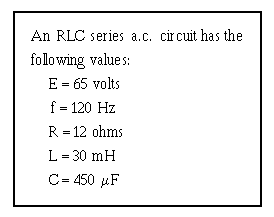
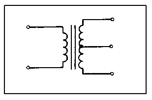
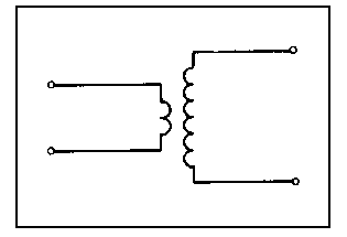
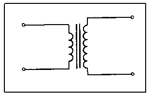
�
�?�
QQQQQQQQQQQQQQQQQQQQQQQQQQQQQQQQQQQQQQQ�
�
21�)1�6/0213�H�/�-2:1�� � �
-,0:�3,� � "$��/./&-�90:;�&:.�;1�
8�-,/�-0)1�9:0;/0�
&,)0)&-/02�-2&��-,)-�)0/�
2</1-292/<�21�-,/�-0)1�9:0;/0�
�&,/;)-2&��21�&:.�;1�)��
�
� )����&,/;)-2&� �
� 8���-0)1�9:0;/0�
������-4G/�
� �� �
�
���
���
���
��
) �������
2���������
&�������������
2���������� ���
�����������
�
� !��
� �
� �
� "��
� �
� �
�
� � � �
�
QQQQQQQQQQQQQQQQQQQQQQQQQQQQQQQQQQQQQQQ�
�
� %�� 6������������������������������� ��� ��
1:-����������������� ��� �$�����
�������� ��� ���� �������������� ���������
�� ������������ �� ������� � ���I�
�
��� ������ ���
��� 1�� ����
��� .������
�� :����
�
� (�� 6������� ���� ������������������ ������
�� ����������������� ��������������������
����� ��� � �I�
�
��� /5� � �����������
��� G� ������������
��� ;����� @ �����������
�� &���������������
�
� ?�� 2�������� ����������������� ��$������
����������������������� �����������I�
�
��� -��� ��������
��� -������������ ��
��� -����� �� �������� ��
�� -����5� � �����������
�
�!7�� 6���� �������������������� ����� ��� �5�
��������� ���������������� ����� ����
�������� ��I�
�
��� G� ����� ��
��� ������������������� ��
��� G� �����5� � �����������
�� �����������5� � �����������
�
� Figure 4B.—Transformer polarity.
�
21�)1�6/0213�H�/�-2:1� �!�$�0/9/0�
-:�923�0/� 8��
�
�!��� -��� ����������������� ��� ��*�+������
����$�����*�+� �������� ���� ��� ������
��������� �� ��� ���������������I�
�
��� *�+�. '������������*�+���
��� *�+��� '���������*�+���
��� *�+�. '������������*�+���
�� *�+��� '���������*�+���
�
$�
�
�7�
�!��� 6� ������������ �� ������ ����� ������
����� �5���� ������� ��������������1:-�
������������������
�
��� .����� �5�
��� .��'����� �5�
��� ������ ���� �5�
�� &���� � ����� �5�
�
�!��� 6���� ������ � ����������������
����� � ����������� ���������������� ���
�� ��� ����������� ��I�
�
��� &�������� ��
��� 2�������� ��
��� ������ ���� �5�
�� .��'����� �5�
�
�! �� )��������� ������������������ ��������!7�
�� �����$�� �������������� �������"��-���
����� � ����������� ��� ����7��6���� ��
������ ����������������������� �� ��I�
�
��� �!7�
��� �77�
��� !77�
�� "77�
�
�!!�� )��������� ����������� �������� � �������
���� ���� �����!������������ �D��7��� ���
���� ������� �����������������6���� ��
������ ������ ����I�
�
��� �77��� ���
��� ��!7��� ���
��� ���7��� ���
�� ���� ��� ���
�
�!"�� )��������� ����������� �������� � �������
���� ����-� ����� ����� ������ ������ ���
�� ���� ��������7!��� ��� �� ���
�����������-������������� ���� ������
���??��������6���� �������� �������������
�������� ���I�
�
��� ���������
��� ���������
��� ���������
�� �������
�
�!%�� )��������� ������������������7�� ������
������������ �� ������"7��� ��������� � ��
-������ ����� ����� ���7��� ����6���� ��
*�+�������������� ����������������� �������
*�+���������� ��������� ��� �� ��� ������
�� ���I�
�
��� *�+�"��$��*�+���������� ������
��� *�+���"$��*�+���7�� ������
��� *�+����$��*�+����7�� ������
�� *�+����$��*�+���7�� ������
�
�!(�� )������������� ����� ������7����������
���� ����������������������������� �������
������ � �������6�������� ������� ��
��������� �����������I�
�
��� "��������
��� !%�������
��� ���������
�� �%�������
�
�!?�� 6���� ��������� � �������������������� ���
����� ���� ��#���� ��� �!(I�
�
��� ���S�
��� "�S�
��� !��S�
�� ?��S�
�
�
-,2���G)&/�./9-�8.)1J�
21-/1-2:1)..4�
�
���
QQQQQQQQQQQQQQQQQQQQQQQQQQQQQQQQQQQQQQQ�
�
21�)1�6/0213�H�/�-2:1�� �"7�
-,0:�3,� �"�$��/./&-�90:;�&:.�;1�
8�-,/�-/0;�-,)-�</�&028/��-,/�-4G/�
:9�G:6/0�.:���21�&:.�;1�)��
�
� )���.:���-4G/�
�
� 8���-/0;��
�"7�� G����� ���� ��
��� �� ���
�� � ���
��� &������ ����
�"��� G������ �� ������
���������� �������
�������� �� ����
��� /������������
����
�"��� G����� �����������
�������� �������
���������
��� ,������� ��
����
� � �� .��'����.����
�
QQQQQQQQQQQQQQQQQQQQQQQQQQQQQQQQQQQQQQQ�
�
�"��� )��������� ������ ����������� ���
���#������� �1:-������ ����������
��������� ��������#���� ����6�����������
� �� �������������� ��$� ���
�������� ����������������������� ������
� ��������#���� ��I�
�
��� 2����������������� �� ����
��� 2��������� ����� �������������
��� 2��������� ��'����� �5�
�� 2���������������������� ����
�
�
-,2���G)&/�./9-�8.)1J�
21-/1-2:1)..4�
QQQQQQQQQQQQQQQQQQQQQQQQQQQQQQQQQQQQQQQ�
�
21�)1�6/0213�H�/�-2:1�� �" �
-,0:�3,� �"%$��/./&-�-,/�
-0)1�9:0;/0�-4G/�90:;�&:.�;1�8�
-,)-�G/09:0;��-,/�-)�J�:0�,)��-,/�
&,)0)&-/02�-2&��</�&028/<�21�
&:.�;1�)��
�
� )���-)�J�
�
� 8��-0)1�9:0;/0�
�����-4G/�
�" �� ������������7�
',@�
��� G�����
�"!�� -������������� ��
����������� ����
��� )����������� ���
�""�� ���������� ����
�� �������� ���
������������ ����
��� )�� ��9��#������
�"%�� &��������������
����� ��������
��������������� �
�� 0�� ��9��#������
�
�
QQQQQQQQQQQQQQQQQQQQQQQQQQQQQQQQQQQQQQQ�
�
�"(�� 6����� ����� ����������� ��� ��
���� ���������������������������������
�������������� ��I�
�
��� 8 ��'������� ���
��� 0��������� ���
��� 8 ��'���������
�� 0��������� ���
�
�"?�� 8����������� ���������'��������� ���� �� �